Safety
Information
Product
Information
Mechanical
Installation
Electrical
Installation
Getting
Started
Menu 0
Running
the motor
Optimisation Macros
Advanced
Parameters
Technical
Data
Diagnostics
UL Listing
Information
82 Unidrive User Guide
www.controltechniques.com Issue Number: 9
E
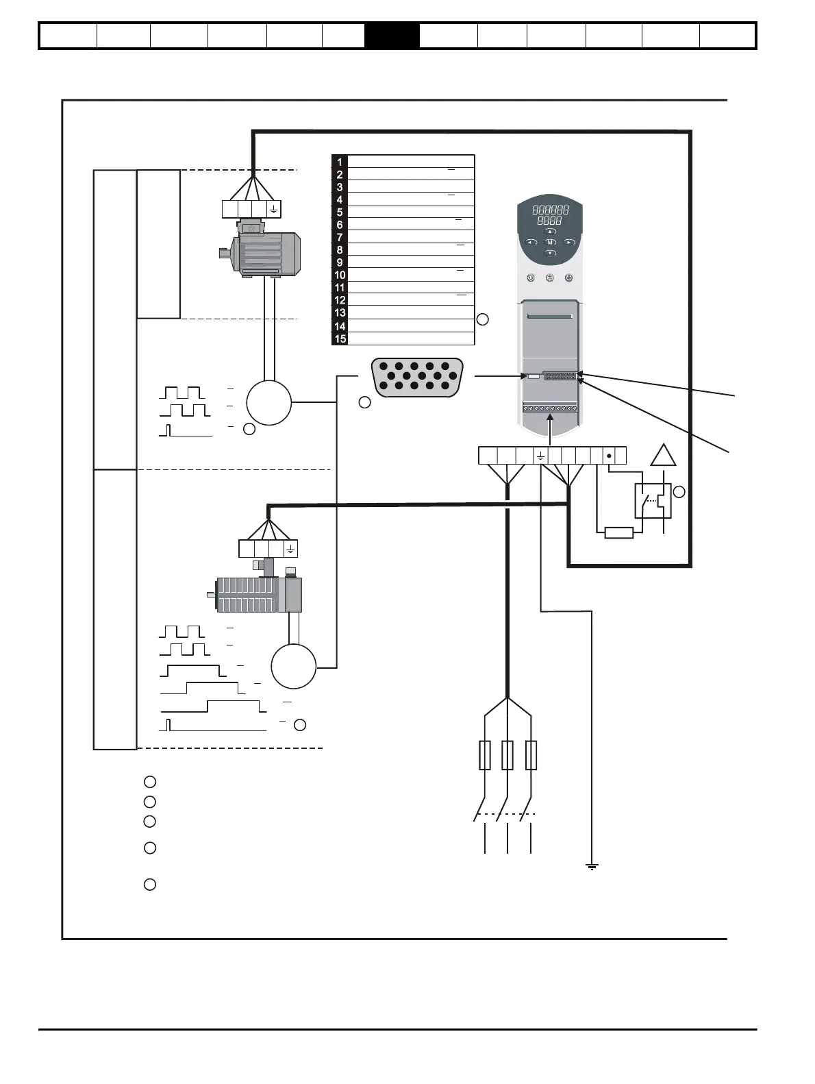
L1 L2 L3
A A
B B
U U
V V
W W
A A
B B
L1 L2 L3 U V W +
_
E
Encoder connector
15 way D-type
5
10
15
1
6
11
Quadrature channel B
Marker pulse channel Z
Commutation channel U
Encoder supply
0V Common
Motor thermistor input
Quadrature channel B
Quadrature channel A
Quadrature channel A
Marker pulse channel Z
Commutation channel U
Commutation channel V
Commutation channel V
Commutation channel W
Commutation channel W
UVW
UVW
Braking
resistor
Fuses
Z Z
Z Z
1
3
4
1
1
2
3
4
Marker pulse optional
Link to 0V if motor thermistor not present
Encoder screening must be connected to 0V at both
the drive end and encoder end of the cable
Thermal overload for braking resistor to protect against
fire risk. This must be wired to interrupt the AC supply in
the event of a fault.
5
!
5
Encoder power supply:
5V, parameter = 0
15V, parameter = 1
3.23
3.23
O
p
e
n
L
o
o
p
C
l
o
s
L
o
o
p
e
d
V
e
c
t
o
r
r
e
S
v
o
Figure 7-1 Minimum connections to get the motor running in any operating mode