Safety
Information
Product
Information
Mechanical
Installation
Electrical
Installation
Getting
Started
Menu 0
Running
the motor
Optimisation Macros
Advanced
Parameters
Technical
Data
Diagnostics
UL Listing
Information
Unidrive User Guide 155
Issue Number: 9 www.controltechniques.com
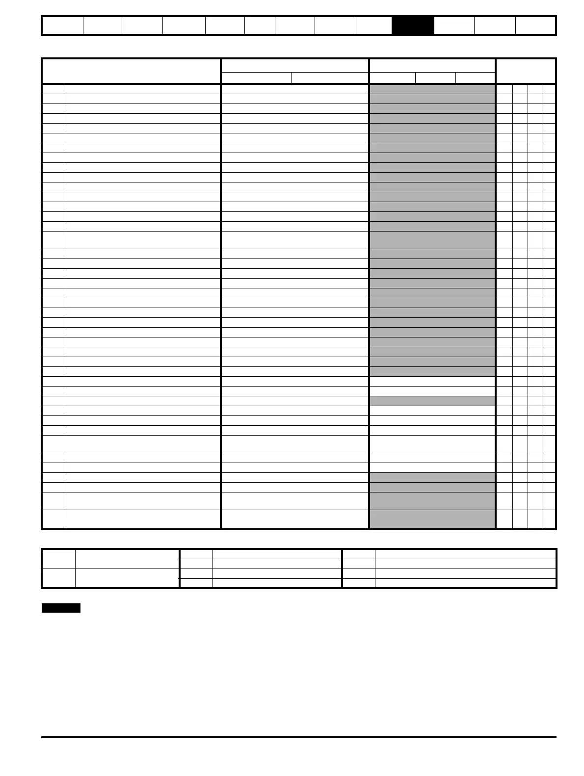
10.10 Menu 10: Status flags / trip log
Where a parameter is represented by a text value, the value in brackets
in the range column is the setting used for serial communications.
Parameter
Range(
Ú)Default(Ö)
Type
OL CL OL VT SV
10.01
Drive normal indicator 0 or 1 RO Bit P
10.02 Drive running indicator 0 or 1 RO Bit P
10.03 At zero speed indicator 0 or 1 RO Bit P
10.04 At or below min. speed indicator 0 or 1 RO Bit P
10.05 Below at-speed window indicator 0 or 1 RO Bit P
10.06 At speed indicator 0 or 1 RO Bit P
10.07 Above at-speed window indicator 0 or 1 RO Bit P
10.08 At 100% load indicator 0 or 1 RO Bit P
10.09 Current-limit active indicator 0 or 1 RO Bit P
10.10 Motor regenerating indicator 0 or 1 RO Bit P
10.11 Dynamic brake active indicator 0 or 1 RO Bit P
10.12 Dynamic brake alarm indicator 0 or 1 RO Bit P
10.13 Direction demanded indicator 0 or 1 RO Bit P
10.14 Direction running indicator 0 or 1 RO Bit P
10.15 AC supply loss indicator 0 or 1 RO Bit P
10.16
Motor thermistor over-temperature
indicator
0 or 1
RO Bit P
10.17 Motor current overload alarm indicator 0 or 1 RO Bit P
10.18 Heatsink temperature alarm indicator 0 or 1 RO Bit P
10.19 Ambient temperature alarm indicator 0 or 1 RO Bit P
10.20 Last trip 0 to 200 RO Txt S P
10.21 Second last trip 0 to 200 RO Txt S P
10.22 Third last trip 0 to 200 RO Txt S P
10.23 Fourth last trip 0 to 200 RO Txt S P
10.24 Fifth last trip 0 to 200 RO Txt S P
10.25 Sixth last trip 0 to 200 RO Txt S P
10.26 Seventh last trip 0 to 200 RO Txt S P
10.27 Eighth last trip 0 to 200 RO Txt S P
10.28 Ninth last trip 0 to 200 RO Txt S P
10.29 Tenth last trip 0 to 200 RO Txt S P
10.30 Max. full-power braking time 0 to 400.0 s 0 RW Uni
10.31 Max. full-power braking interval 0 to 25.0 min 0 RW Uni
10.32 External trip active indicator 0 or 1 RO Bit
10.33 Drive reset 0 or 1 0 RW Bit
10.34 Number of auto- reset attempts 0 to 5 0 RW Uni
10.35 Auto-reset time delay 0 to 25.0 s 1.0 RW Uni
10.36
Hold drive healthy until last auto-reset
attempt select
0 or 1 0 RW Bit
10.37 Stop drive on non-important trips 0 or 1 0 RW Bit
10.38 User trip 0 to 200 0 RW Uni P
10.39 Braking-energy overload accumulator 0 to 100.0 % RO Uni P
10.40 Status word 0 to 32,767 RO Uni P
10.41
UD78 auxiliary power supply active
indicator
0 or 1
RO Bit P
10.42
IGBT junction temperature above 135
o
C
indicator
0 or 1
RO Bit P
RO Read Only parameter
Uni Unipolar variable parameter R Reset required for new value to take effect
Bi Bipolar variable parameter S New parameter-value saved at power-down
RW Read / Write parameter
Txt Text variable parameter P Protected; forbidden as destination parameter
Bit Bit parameter FLC Full-load current (max. continuous), Pr 11.32 {0.33}
NOTE