Safety
Information
Product
Information
Mechanical
Installation
Electrical
Installation
Getting
Started
Menu 0
Running
the motor
Optimisation Macros
Advanced
Parameters
Technical
Data
Diagnostics
UL Listing
Information
56 Unidrive User Guide
www.controltechniques.com Issue Number: 9
The output voltage at terminal 13 is 5V when Pr 3.23 is set at 0 (default).
When Pr 3.23 is set at 1, the output voltage will become 15V. This could
damage encoders that require a 5V supply.
Termination resistors should be disabled by setting Pr 3.24 to 1 if the
encoder output is 15V.
This terminal is connected internally to terminal 8 of the signal connector
Connect only one of these terminals to a motor thermistor. Analog input
3 must be in thermistor mode, Pr 7.15 = th.Sc (9) or th (10).
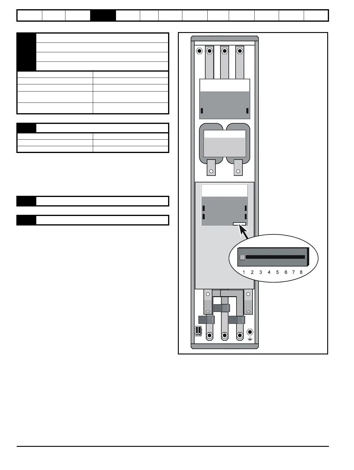
4.11 Configuring a Unidrive size 5 system
The following must be performed in order to configure a Unidrive size 5
system:
• Each power module must be given a unique address.
• The control module must be notified of the number of power
modules it is to control.
• The new settings must be saved in the control module software.
4.11.1 Configuring the power modules
To set the address on a power module, set the slide switch to the
required address number, see Figure 4-19 for the position of the switch.
Ensure that each power module in a multiple module system has its own
unique address number. See Table 4-6 for example configuration
settings.
Figure 4-19 Location of the power module address switch
7 Frequency output FOUT
8 Frequency output FOUT\
9 Direction output DOUT
10 Direction output DOUT\
Type EIA422 differential receivers
Maximum data rate 250kHz
Line termination components
120
Ω
Absolute maximum applied voltage
relative to 0V
+15V to -10V
Absolute maximum applied differential
voltage
±25V
13 Encoder supply
Supply voltage +5.15V or +15V (selected by Pr 3.23)
Voltage tolerance ±2%
Nominal output current 300mA
14 0V common
15 Motor thermistor input
IN96
Phase-control board
DC-bus choke
IN95
Interface board