Safety
Information
Product
Information
Mechanical
Installation
Electrical
Installation
Getting
Started
Menu 0
Running
the motor
Optimisation Macros
Advanced
Parameters
Technical
Data
Diagnostics
UL Listing
Information
178 Unidrive User Guide
www.controltechniques.com Issue Number: 9
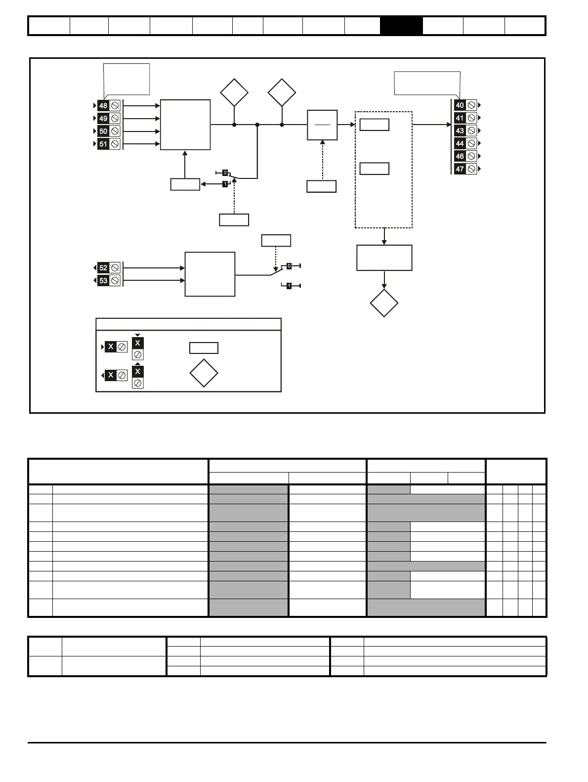
Figure 10-26 Menu 16 UD53 logic diagram
UD53 Resolver small option module parameter list
6
6
6
6
6
SIN low
SIN high
COS low
COS high
Decoder
Resolver
SIN and COS
inputs
16.09
1
2
[16.07]
16.02
eso
ver
rpm
eso
ver
position
16.03
16.05
16.07
Resolver
phase offset
Resolver
phasing test
Simulated-encoder
output scaling
16.08
Simulated-
encoder F/D
output enable
16.12
Simulated-
encoder Z
marker-pulse
outputs
synchronisation
disable
Synchronisation
control logic
16.13
Simulated-encoder Z
marker-pulse outputs
synchronisation
inactive indicator
A(F)
/A(/F)
B(D)
/B(/D)
Z
/Z
Simulated-encoder
output
0.XX
0.XX
Key
Read-write (RW)
parameter
Read-only (RO)
parameter
Input
terminals
Output
terminals
The parameters are all shown at their default settin
s
6
Excitation high
Excitation low
Excitation
3:1
2:1
16.10
Resolver
turns ratio
select
Parameter
Range(
Ú)Default(Ö)
Type
OL CL OL VT SV
16.01
Option module code 0 to 100 1ROUniP
16.02 Resolver rpm ±30,000 rpm RO Bi P
16.03 Resolver position
0 to 16,384 revolutions/
16,384
RO Uni P
16.05 Resolver phasing test 0 or 1 0RWBit
16.06 Encoder select for encoder simulation 0 or 1 0RWBit
16.07 Encoder output scaling 0 to 15 (power of 2) 0RWUni
16.08 F/D output select 0 or 1 0RWBit
16.09 Phasing offset 0 to 6143 RW Uni S P
16.10 Low ratio resolver select 0 or 1 0RWBit
16.12
Encoder marker simulation
synchronisation disable
0 or 1 0RWBit
16.13
Encoder simulation marker
synchronisation inactive
0 or 1 RO Bit P
RO Read Only parameter
Uni Unipolar variable parameter R Reset required for new value to take effect
Bi Bipolar variable parameter S New parameter-value saved at power-down
RW Read / Write parameter
Txt Text variable parameter P Protected; forbidden as destination parameter
Bit Bit parameter FLC Full-load current (max. continuous), Pr 11.32 {0.33}