Safety
Information
Product
Information
Mechanical
Installation
Electrical
Installation
Getting
Started
Menu 0
Running
the motor
Optimisation
Macros
Advanced
Parameters
Technical
Data
Diagnostics
UL Listing
Information
Unidrive User Guide 101
Issue Number: 9 www.controltechniques.com
9 Macros
9.1 Introduction
Application macros are pre-programmed parameter sets. They minimise
the number of different parameters to be set during start-up. The control
terminals are configured for specific applications and commonly used
parameters are cloned into Menu 0.
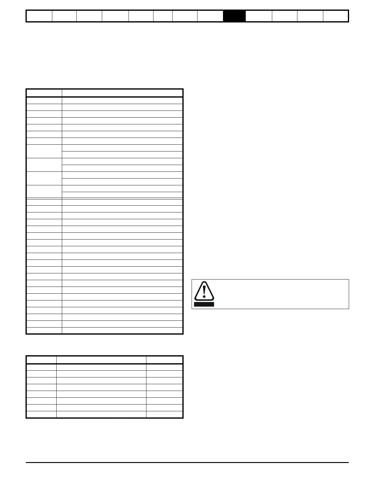
The following parameters are common to each macro:
The following macros are available.:
* Macro 8 is only available in closed loop vector or servo operating
modes.
When using Unidrive VTC, only macros 1, 2, 3 and 5 are available. For
macro differences when using Unidrive VTC, see section 9.5 Unidrive
VTC macro differences on page 122.
Macro 1 – Easy Mode
The Easy mode macro gives the simplest operation of the drive for basic
applications. It is identical to the default condition except that menu 0
has less parameters.
Macro 2 – Motorised potentiometer
The Motorised potentiometer macro enables the drive's own internal
motorised potentiometer to control the speed of the drive via digital
inputs. A digital input selects between an analog speed reference and
the motorised potentiometer reference.
Macro 3 – Preset frequencies / speeds
The Preset reference macro enables the use of preset references to
control the speed of the motor via digital inputs. A digital input selects
between an analog speed reference and the preset references.
Macro 4 – Torque control
The Torque control macro configures the drive for use in Torque control
mode, selectable via a digital input. Analog input 1 is configured for the
torque reference. When in speed control analog 2 is the speed
reference. When in torque control with the drive in closed loop mode
analog input 2 is the speed override reference. Enabling torque mode
with the drive in open loop mode will put the drive in to pure torque
control. In closed loop mode the drive will be put in to torque control with
speed override.
Macro 5 – PID (set-point control)
The PID control macro enables the drive's own internal PID controller to
control the speed of the motor. Analog input 1 is configured for the main
speed reference, analog input 2 is the PID reference and analog input 3
is the PID feedback. A digital input selects between an analog speed
reference and the PID control.
Macro 6 – Axis-limit control
The Axis limit control macro configures the drive for use with limit
switches so that the drive is stopped when a position limit has been
reached. The speed reference can be either unipolar or bipolar.
Macro 7 – Brake control
The brake control macro configures the drive to apply or release a
mechanical brake on a motor in a crane or hoist application. The drive
issues a brake release signal via a digital output when the relevant
conditions are met.
Macro 8 – Digital lock / shaft orientation
Only available in closed loop vector or servo operating modes.
Digital lock:
The drive operates as a slave in a closed loop master-slave system. The
slave motor is digitally locked to the master motor.
Shaft orientation:
The motor speed is controlled in the same way as for default operation,
but the motor shaft can be orientated to a specified angular position
before and/or after running the motor.
Pr Function
0.00 Configuration and saving
0.01 Minimum frequency/speed clamp
0.02 Maximum frequency/speed clamp
0.03 Acceleration rate
0.04 Deceleration rate
0.05 Reference
selector
0.06 Current limit
0.07
OL> Voltage mode
selector
CL> Speed-loop proportional gain
0.08
OL> Boost voltage
CL> Speed-loop integral gain
0.09
OL> Dynamic V/f
select
CL> Speed-loop derivative gain
0.10
OL> Estimated motor speed
CL> Motor speed
0.31 Macro number
0.32 Serial comms. mode
0.33 Drive rated current (FLC)
0.34 User security code
0.35 Keypad reference
0.36 Serial comms. baud rate
0.37 Serial comms. address
0.38 Power up parameter display
select
0.39 Synchronise to a spinning motor
0.40 Autotune
0.41 PWM switching frequency
selector
0.42 Motor – number of poles
0.43 Motor – power factor
0.44 Motor – rated voltage
0.45 Motor – rated full load rpm
0.46 Motor – rated current
0.47 Motor – rated frequency
0.48 Drive operating mode
selector
0.49 Security status
0.50 Drive software version
Macro Description Code
1 Easy mode 2001
2 Motorised potentiometer 2002
3 Preset frequencies / speeds 2003
4 Torque control 2004
5 PID (set-point control) 2005
6 Axis-limit control 2006
7 Brake control 2007
8 * Digital lock / shaft orientation 2008
Where a safety hazard may exist the drive alone must not be
permitted to release the brake. An independent safety
interlock must be provided to ensure safe operation in the
event of drive failure or incorrect operation.
WARNING