Safety
Information
Product
Information
Mechanical
Installation
Electrical
Installation
Getting
Started
Menu 0
Running
the motor
Optimisation Macros
Advanced
Parameters
Technical
Data
Diagnostics
UL Listing
Information
Unidrive User Guide 39
Issue Number: 9 www.controltechniques.com
N
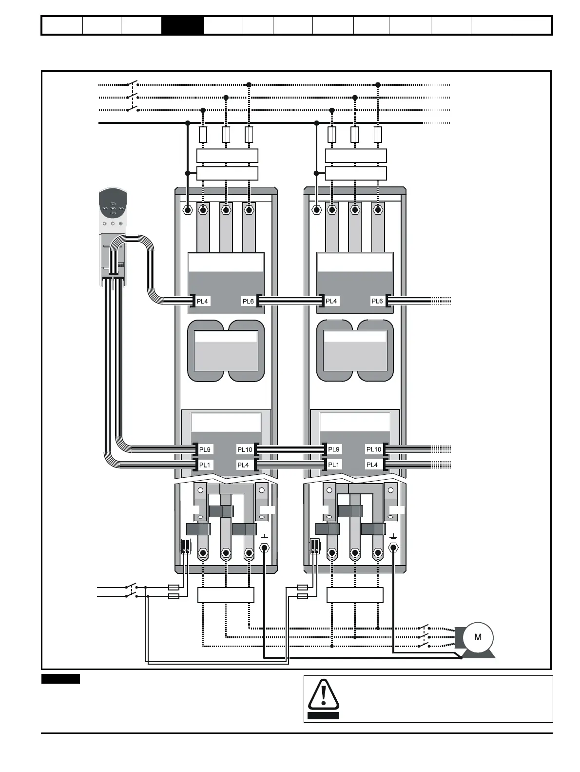
When using Unidrive size 5 with multiple power modules, a sharing
choke must be fitted on the output of each drive as shown. The
specification for the choke is given in Chapter 11 Technical Data on
page 190 and it should be sourced locally.
IN96
Phase-control board
DC-bus choke
IN95
Interface board
W
V
U
L1
L2
L3
UWVUWV
Contactor / Isolator
IN96
Phase-control board
DC-bus choke
IN95
Interface board
Ground
Sharing choke Sharing choke
AC supply for fan
(when fitted)
Control
module
Power
module
10-way
16-way
26-way
Power
module
10-way
16-way
26-way
Contactor /
Isolator
Fuses Fuses
Optional RFI filter
Optional line reactor
Optional RFI filter
Optional line reactor
+DC
-DC -DC
+DC
4.1.1 Unidrive size 5 control / power module connections
Figure 4-3 Unidrive size 5 ribbon cable and sharing choke inter-
NOTE
Ensure that the fan and power module can be isolated from
the AC supplies. Isolation from the supplies must be
interlocked, or a warning must be displayed indicating that
two separate supplies are present.
WARNING