2-11
Place the lamp canopy support in each side
wall directly below the cavities (see figure 2.26).
Ensure the clips are secure and firmly locked.
6. Install the canopy. (Item H)
Carefully slide the canopy in until the screw
socket located in the center of each side
of the lamp canopy locks into the support
center hole. Plug the canopy in. (See figure
2.27 and 2.28.)
Only the top connector must be
used with this kit. Keep all
unused connectors capped.
Figure 2.27: Air filter installed in its
compartment. Again, notice the position of
the lamp canopy support with respect to
the filter.
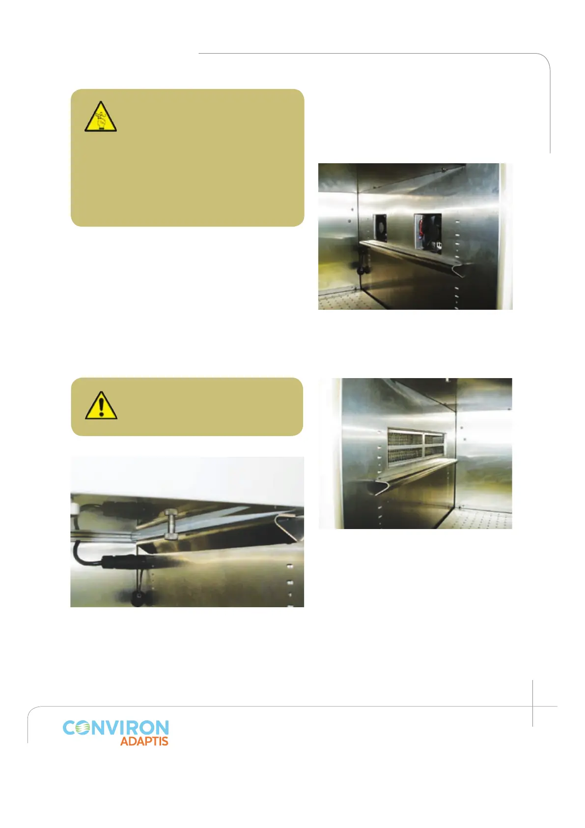
Figure 2.26: Fans installed and plugged in
to their compartments. Notice the position
of the lamp canopy support with respect to
the fans.
Figure 2.28: Lamp canopy locked into the support
and plugged in.
CAUTION: The lamp canopy for
the PG Kit is predetermined by
the position of the cooling fans
on the side wall. The canopy
must be installed in such a way
that the air fans align with the
canopy ports. Failing to do so
may result in user injury or
improper chamber operation.
 Loading...