2-13
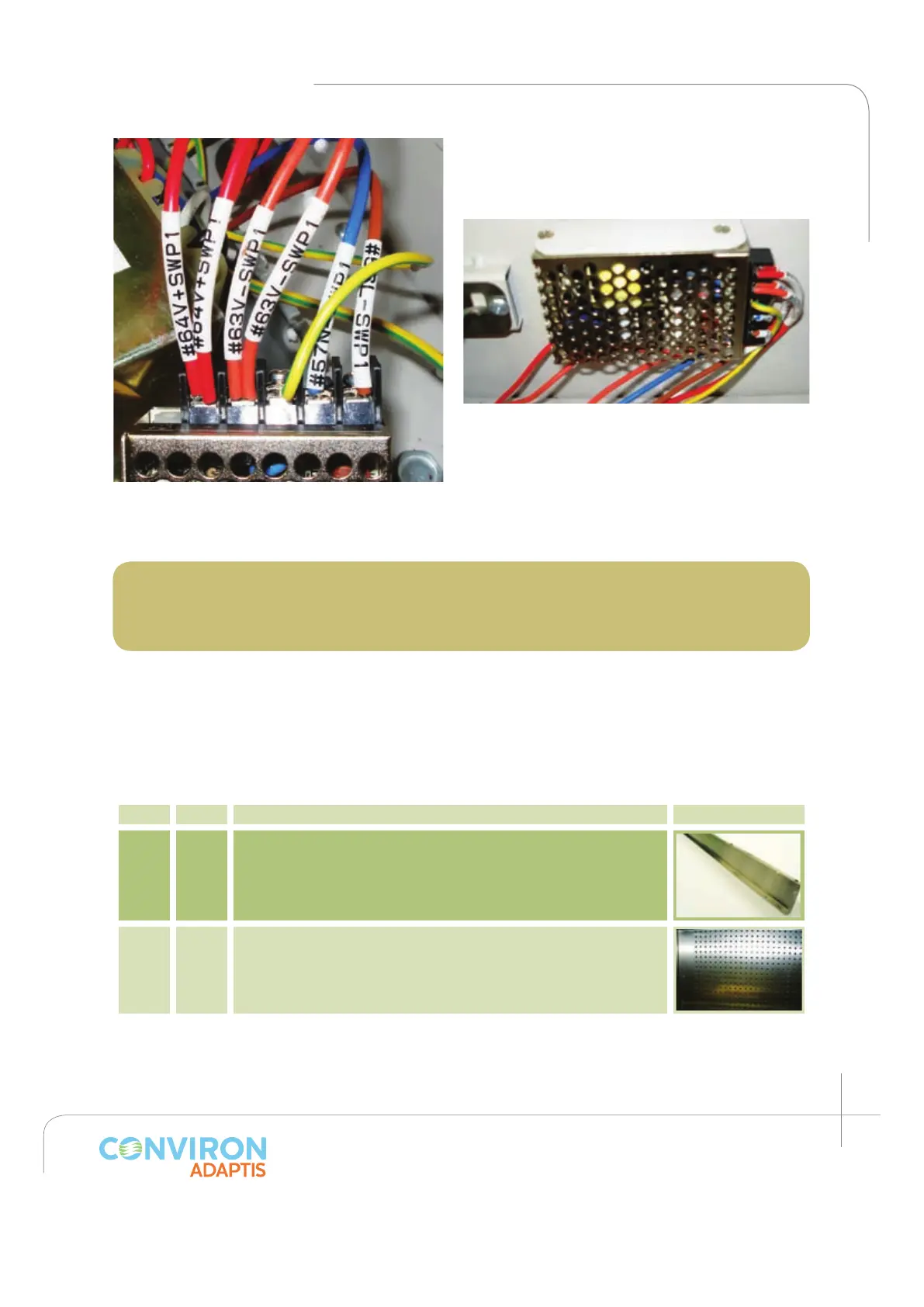
Install the AC/DC converter in to the RIGHT
side wall as shown with the two (2) screws
(item L) provided. (See figure 2.31)
The chamber is now ready to operate. Please
carefully read the Chamber Start-Up Instructions
before proceeding with the start-up.
Note: The maximum operating levels of light for this Kit must be set at the controller.
To edit the factory default setting, follow the set up instructions in the CMP 6010
Operator’s Manual Section 6: Options -- Setup.
2.3 Incubator
Kit parts
The following list comprises the components for the IN kit.
Item Qty Description Picture
A 1 Back plenum bottom
B 1 Back wall plenum
Figure 2.30: Notice the wire labels: from left to
right: +VDC; -VDC; ground, neutral, Line.
Figure 2.31: AC / DC converter installed.
 Loading...