May 2009 | Revision 6.0
2-10
CHAPTER 2.0 | KIT INSTALLATION
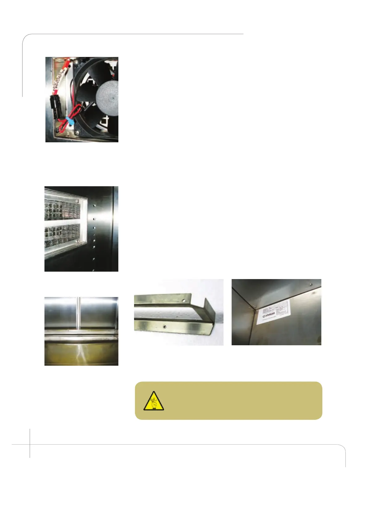
Figure 2.21: The fan wire
connector has a single
orientation connection –
ensure the connections
snap together.
Figure 2.22: Canopy air
inlet filter is showed.
Figure 2.23: View after
Installing the back
plenum bottom panel.
Figure 2.24; Correct position of
the back plenum bottom panel.
Figure 2.25: Shows in detail the
back plenum installed above the
fan housing.
CAUTION: Ensure at least 2” of free space
around the side walls of the chamber interior to
facilitate proper air circulation whenever possible.
4. Install the back wall plenum. (Item B)
The back wall plenum can be installed. (See figure 2.23
and 2.24) It must be installed with the short flanges
toward the unit’s back wall. Loosen the six (6) screws at
the back of the fan housing. Install the plenum with the
largest flange at the top facing the door, between the fan
housing and the coil drip pan. Ensure the grooves in the
flange insert around the screws. (For ease of installation
use the handle provided at the top). Secure the back wall
plenum to the side supports utilizing the eight (8) screws
(item C) provided with the kit. Then refasten the six (6)
screws at the back of the fan housing (see figure 2.25).)
5. Install the lamp canopy supports. (Item G)
The PG kit uses ambient air to cool the light canopy. As the
air circulates through the canopy it absorbs heat which is
then expelled back to atmosphere. This enables maximum
light output throughout the entire temperature range, since
the lamps are cooled by ambient air, while it also helps to
ease the heat load on the refrigeration system.
 Loading...