2-9
Note: This step may require the installer to first pass the
fan cables from the top down. The wires can be connected
to their power supply on a later step.
Once the fans are mounted into the compartment, connect the
wires (Item M) as shown (see figure 2.21).
Note: Install the fans such that the air flows from inside
the chamber to the outside and such that the wires are
located in the most convenient position. (See figure 2.20)
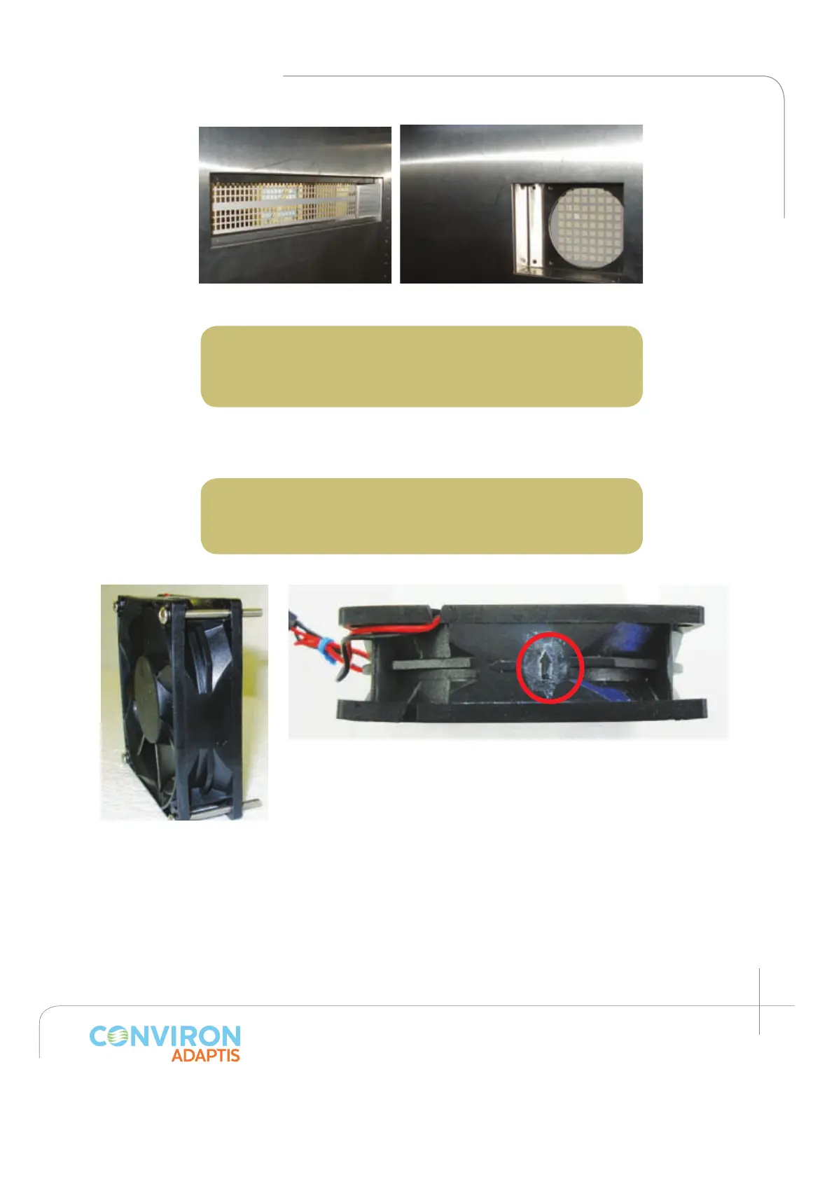
Figure 2.18a: Air inlet.
Figure 2.18b: Fan compartments.
Figure 2.19: Canopy
cooling fan showed
with four screws (item J)
before installation.
Figure 20: Arrow indicates the airflow direction – ensure it points
towards the chamber exterior.
2. Install the canopy air inlet filter. (Item E)
Using the screws (item C), install the air filter such that the
filter mesh sits flush with the inside wall. (See figure 2.22.)
3. Install the back plenum bottom panel.
Five (5) screws (item C) are required to install the back
plenum bottom. Firmly screw the panel into the back wall
(see figure 2.23). Note the four holes in the front of the
support where the back plenum will be fastened.
 Loading...