May 2009 | Revision 6.0
2-18
CHAPTER 2.0 | KIT INSTALLATION
E 2 Wire shelf
F 2 Lamp canopy
G 4 Canopy support
Kit assembly instructions
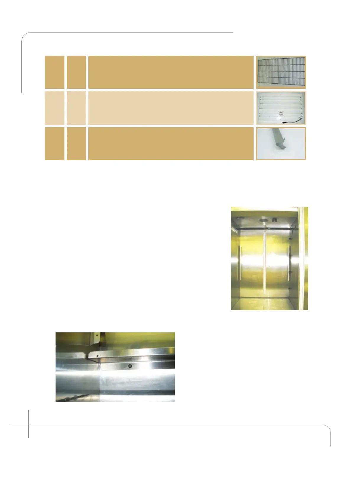
Open the cabinet door, and visually inspect the cabinet. Ensure the two fan cavities on the
right side wall are covered as well as the air inlet on the left hand side (see figure 2.39).
1. Install the back plenum bottom panel: (Item A)
This panel is very important because it directs the airflow
through the plenum at equal pressure. A loose installation
and the airflow distribution will not be even. Five (5) screws
(item C) are required to install the back plenum bottom
panel. Firmly screw the panel into the back wall with five
(5) screws (see figure 2.40). Ensure that the drain holes are
never plugged.
2. Install the back wall plenum. (Item B)
Now the back wall plenum can be installed. It must be
installed with the short flanges toward the unit’s back wall.
Loosen the six (6) screws at the back of the fan housing.
Install the plenum with the largest flange at the top facing
the door, between the fan housing and the coil drip pan.
Ensure the
grooves in the flange insert around the
screws. (For ease of installation use the
handle provided at the top). Secure the
back wall plenum to the side supports
utilizing the eight (8) screws (item C)
provided with the kit. Then refasten the six
(6) screws at the back of the fan housing
(see figure 2.41).
Figure 2.40: A1000 view after Installing the
back plenum bottom panel.
Figure 2.39: A1000
empty cabinet.
 Loading...