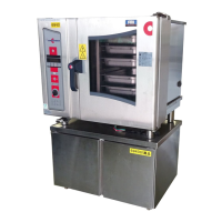
Service Handbook OEB/OES/OGB/OGS
6.1.3 Arrangement module replacement
i
Information:
Arrangement module part no.: 5009301
The arrangement module is the central network part (12 V) for all other
electronic components and the 12 V fan.
Check:
When the green LED 42 on the front side of the plate is lit or blinking, the
arrangement module is operating correctly. (module self-checking)
When the red LED 41 is lit, the arrangement module is defect and must be
replaced. (module self-checking)
LED 41 and 42 see 6.1.5 Positions of the LEDs on the Controls.
Safety:
When working on the operation module, make sure that the main power
supply is disconnected (an all-pole isolation switch with a minimum contact
opening of 3mm must be located close to the unit- on site) and ensured
against switching on again.
Attention: When the unit is with power, the arrangement module carries live
voltage.
This work should only be performed by a CONVOTHERM trained electrician.
Instructions: Arrangement module removal
Remove the front plate from operation module and lay it next to unit (see
"6.1.1 Operation module removal").
Pull out both flat plugs 2 to the power supply for the control module from the
arrangement module 4.
Unclip both output 12 V cables.
Unscrew the knurled nuts 3 of the arrangement module 4 and pull the
arrangement module straight and evenly out from the fastening bolts.
Attention: Don‘t lose distancing bolts 1.
Instructions: Arrangement module assembly
Place the arrangement module 4 onto the 4 fastening bolts (all distancing
bolts 1 present!) straight and evenly onto the assembly panel.
Screw on the 4 knurled nuts 3 and tighten.
Plug in both flat plugs 2 to the power supply of the control module.
Clip on both output 12 V cables.
Assemble the assembly panel with the control module into the connection
area (see "6.1.1 Operation module removal").
AS/11-2011 6_01e_Electronic Control Board installation_c
Page 5 / 8
 Loading...
