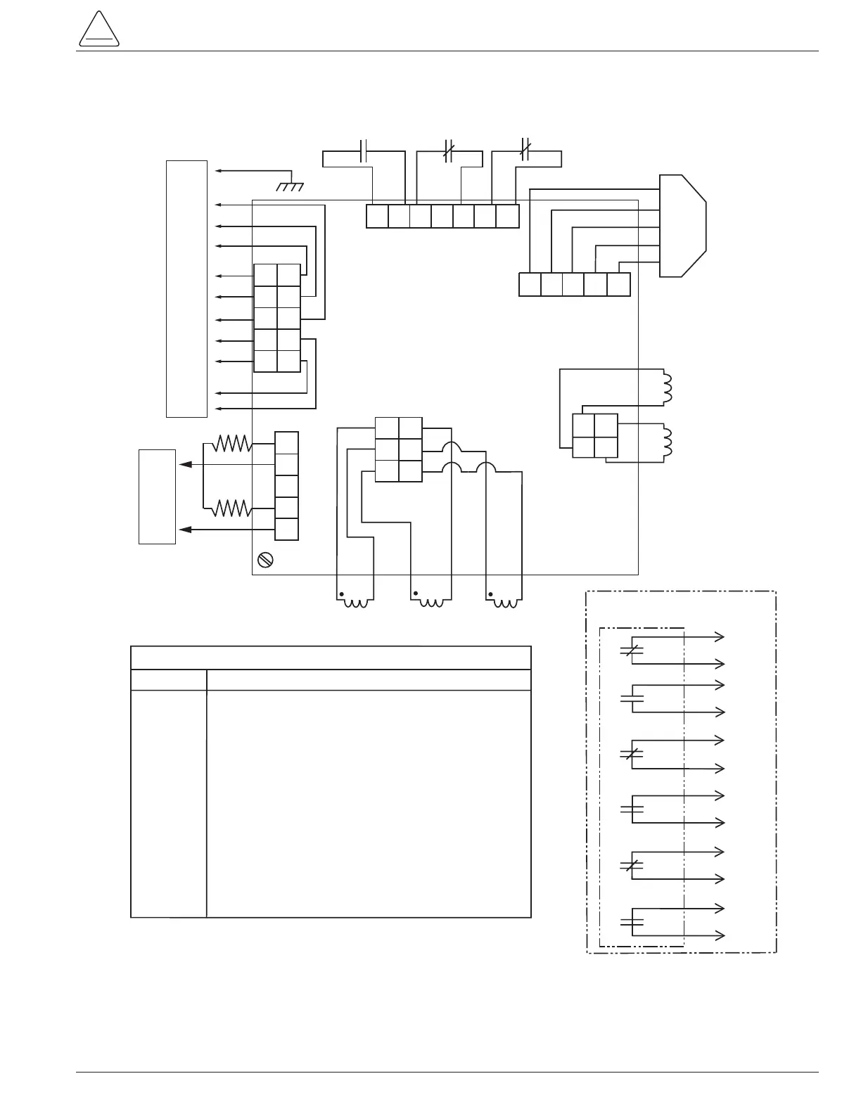
LEGEND
SYMBOL DESCRIPTION
AB Actuator Circuit Board
AS Auxiliary Switch - 3 Stage
CC Close Coil
TC Trip Coil
MS1 Microswitch, Contact Position Indicator
MS2 Microswitch, Contact Position Indicator
MS3 Microswitch, Open Handle - Disables Closing Circuit
52a or a Contact - Open When Unit is Open
52b or b Contact - Closed When Unit is Open
R1 Receptacle, Control - 14-Pin Female
R2 Receptacle, 2-Pin Male *Polarity Independent
R3 Receptacle, Auxilliary Switch - 14-Pin Male
H1 Resistive Heater
H2 Resistive Heater
CT Current Transformer
R3-D
R3-C
b
R3-B
R3-A
a
R3-H
R3-G
b
R3-F
R3-E
a
R3-M
R3-L
b
R3-K
R3-J
a
1
2
3
4
5
6
7
8
9
10
11
12
"AS"
AUXILIARY SWITCH
ACCESSORY
ACTUATOR
CIRCUIT BOARD
"AB"
R2-A*
R2-B*
R1-M
1
2
4
3
5
"P4"
"H1"
1
2
"H2"
1
2
"CC"
+
–
+
–
"TC"
BLK
BLK
RED RED
"P6"
A2
A1
A3
"P3"
B2
B1
B3
AØ CT
BØ CT
CØ CT
X1
X1
X1
R1-G
R1-K
R1-J
R1-H
R1-D
R1-C
R1-E
R1-A
R1-F
R1-B
A1
A2
A4
A3
A5
"P2"
B1
B2
B4
B3
B5
"P1"
2
1
3
4
5
6
7
"MS1"
N.C.
52a
COM
N.O
.
"MS2"
52b
COM
"MS3"
COM
N.C.
Position
Sensor
5
4
3
2
1
4
5
3
2
1
"P8"
Microswitches shown with recloser
contacts OPEN and yellow handle
in the UP position.
Control Cable Receptacle
Auxiliary Input Power Receptacle
 Loading...