Voltage Protection (120 Vac-based)
Voltage protection functionality is included as standard on
Form 5/Triple-Single controls. A recloser trip is issued for
under and over voltage conditions when the monitored
voltage falls outside user specified limits for a selectable
time. Response mode includes:
• any single-phase
• all three phases
• single-phase with three-phase inhibit.
Response mode facilitates protection against a single
phase condition common when a high-side fuse operates
on a distribution transformer. Parameters are also avail-
able to provide auto restoration after a trip. A voltage
alarm is available and can be configured for notification.
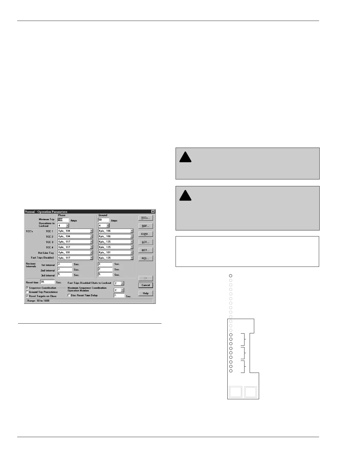
Protection Profiles
Four separate protection profiles are included to allow the
user to adapt overcurrent settings for varying system con-
ditions such as load, live line work or weather. The active
profile is selected from the operator panel, the interface
software or SCADA (see Figure 11). Each profile has 14
TCC specifications plus reclose intervals, sequence coor-
dination and reset times to maintain independent protec-
tion parameters.
Power Metering
Power metering includes single- and three-phase Watts,
VARS, KVARS, KWH measurements, and the per phase
and total system Power Factor (PF).
Power Factor Sign Metering
This feature allows a user to configure the sign that is
applied to the power factor. The user selects between the
definition of power factor (cosine of angle between current
and voltage) or the power factor sign following power flow.
Trip Failure Detection
The Trip Failure Detection feature is an internal diagnos-
tic alarm for verifying the proper operation of circuit trip-
ping and fault clearing of the recloser. Trip Failure
detection indicates the recloser has failed to trip all
phases following a trip signal from the control. Failure to
trip is assumed if a current of at least 10 Amps is detected
approximately 2 seconds after the trip signal is initiated.
Upon activation of the feature the following four LEDs
flash 1 second on, 1 second off (see Figure 12):
RECLOSER MALFUNCTION
RECLOSER CLOSED
RECLOSER OPEN
CONTROL LOCKOUT
Kyle Form 5/Triple-Single Microprocessor-Based Recloser Control Installation and Operation Instructions
16
Figure 12.
RECLOSER MALFUNCTION, OPEN, CLOSED, and
LOCKOUT LEDs will blink for the affected phase as
indication of Trip Failure.
Figure 11.
Interface software sample protection profile.
DANGER: Explosion. Stay clear of a recloser
that is in a trip failure mode. A recloser in trip fail-
ure mode may explode resulting in death or severe per-
sonal injury. T271.0
IMPORTANT: The recloser must be isolated and de-
energized immediately upon detection of trip failure.
Follow proper procedures and safety practices to iso-
late and de-energize the recloser.
WARNING: Hazardous voltage. This device is
not a substitute for a visible disconnect. Follow all
locally approved safety practices. Failure to follow
proper safety practices can result in contact with high
voltage, which will cause death or severe personal
injury. G112.1