The Trip Failure Detection alarm may be triggered from
many potential sources including mechanical, electrical,
control, or interrupter failure. Interrupter failure may
include loss of vacuum in a vacuum interrupter.
To clear Trip Failure Alarm, depress and hold the RESET
TARGETS/RESET MAX CURRENTS keypad for 3 sec-
onds. This also resets targets and demand currents.
Note: There is no remote reset available with the trip failure
detection feature. It cannot be remotely turned off.
When the trip failure alarm is activated, an event is
recorded and a status alarm activated (if enabled) and
preserved during system resets.
Manual Close Delay
Manual Close Delay provides a delay from the time that
the manual CLOSE button is pushed to the time the man-
ual close operation is performed. The CLOSED LED for
the affected phase blinks indicating the feature is active.
See Figure 13.
The delay is programmable from 0 to 60 seconds in one
second increments. A programmed delay value can be
overridden for immediate closing by pressing the CLOSE
button a second time.
An active Manual Close Delay can be canceled by press-
ing the TRIP/LOCKOUT button.
The default setting has the feature disabled (0 seconds).
Voltage Metering
Six voltages (3-source and 3-load) are metered as stan-
dard on the Form 5/Triple-Single control. The user selects
either line-to-neutral or line-to-line values from the control
operator panel, interface software, or serial communica-
tions. The type of value is changed by selecting “Voltage
Configuration” in the “Hardware” setup portion of the inter-
face software.
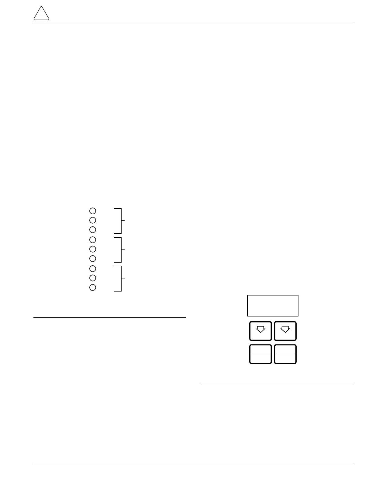
Fast Trips Disabled
Fast Trips Disabled provides the user a quick and efficient
method for reducing momentary interruptions or “blinks”.
When activated from the front keypad (Figure 9), pro-
grammed trips to lockout will time according to the
selected time-current curve for Fast Trips Disabled. This
curve is programmable for both phase and ground on
each protection profile. A separate trips-to-lockout setting
is also provided.
Histograms
Demand metered voltages and currents can be reported
using the histogram tool. It displays the number of occur-
rences of a variable versus its value within user-defined
minimum and maximum limits. Date and time are
recorded for the maximum and minimum demand values.
Reverse Power Flow
Feeder load monitoring is enhanced with the inclusion of
the power flow monitoring feature. When power flow from
the load to the source side of the recloser is detected, the
control and illuminates a front-panel indicator. Response
time to a reverse power condition is one second. An alarm
is also available for remote interrogation.
Note: Voltage sensor polarity must be correct for reverse
power flow to function properly.
Harmonic Analysis
Extensive harmonic analysis is performed by the Form
5/Triple-Single control for both currents and voltages.
Analysis is performed on-line (updates every 30 seconds)
or demand integrated to user-specified time values. The
Total Harmonic Distortion (THD) for current and voltage is
available from the operator panel display (Figure 14) while
complete analysis, including graphing capabilities, is pro-
vided from the Form 5/Triple-Single interface software.
Event Recorder
The Event Recorder maintains a log of operating events
for later readout and analysis by the user. Approximately
500 events can be stored in non-volatile memory. For
each event type, time of occurrence, and other relevant
information is stored. When the event recorder has
reached capacity, the oldest event is deleted as a new
event is added.
S280-42-3
17