EasyManua.ls Logo

Cooper Kyle Form 6 User Manual

Cooper Kyle Form 6
12 pages
To Next Page IconTo Next Page
Page #1 background imageLoading...
Page #1 background image
1
Form 6 Recloser Control Disassembly,
Reassembly, and Testing Instructions
Reclosers
Service Information
Safety Information ..................................................... 2
Hazard Statement Definitions ................................ 2
Safety Instructions .................................................. 2
Product Information .................................................. 3
Introduction ............................................................ 3
ANSI Standards ..................................................... 3
Quality Standards ................................................... 3
Acceptance and Initial Inspection .......................... 3
Handling and Storage ............................................ 3
Description ............................................................. 3
Disassembly .............................................................. 4
Disassembly Instructions ....................................... 4
Open the Module ................................................... 5
Remove/Replace CPU Board ................................ 5
Remove/Replace Comms. Accsy. Board Only ....... 6
Remove/Replace I/O Board ................................... 7
Remove/Replace Power Supply or RIF Board ...... 7
Remove/Replace Analog Board ............................. 8
Reassembly ............................................................... 8
Reassembly Instructions ........................................ 8
Place Module in Control ......................................... 8
Before Placing the Control Into Service ................. 9
Installation ................................................................. 9
Initial Programming Prior to Installation ................. 9
Testing ........................................................................10
Testing Instructions ................................................10
Communication Ports .............................................10
Contact Inputs/Outputs ..........................................10
Testing with Type MET Tester ................................11
Additional Information ..............................................12
Replacement Kits ...................................................12
Factory-Authorized Service Centers ......................12
Factory Testing and Troubleshooting Classes .......12
Contents
S280-70-11
Printed in USA
1
August 2005 • Supersedes 6/04
Figure 1.
Kyle
®
Form 6 Pole Mount, Yard Mount, and Rack Mount recloser controls.
Question and Answer IconNeed help?

Do you have a question about the Cooper Kyle Form 6 and is the answer not in the manual?

Cooper Kyle Form 6 Specifications

General IconGeneral
BrandCooper
ModelKyle Form 6
CategoryIndustrial Electrical
LanguageEnglish

Summary

Safety Information

Safety Instructions

General safety precautions and warnings for operating and maintaining the recloser control equipment.

Hazard Statement Definitions

Explanation of hazard symbols (Danger, Warning, Caution) used throughout the manual.

Product Information

Introduction to Product

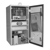
Overview of the Form 6 Recloser Control and its purpose.

Applicable Standards

Lists the ANSI standards the reclosers are designed and tested against.

Quality Standards and Inspection

Details quality management system and initial inspection procedures upon receipt.

Handling and Storage

Guidelines for safely handling and storing the recloser control unit.

Product Description and References

Describes the Form 6 control and lists related service information documents.

Disassembly Procedures

General Disassembly Instructions

Steps for safely removing the Form 6 recloser control from service.

Opening the Control Module

Procedure for opening the recloser control module to access internal components.

CPU Board Replacement

Step-by-step guide for removing and replacing the CPU board.

Communications Accessory Board Replacement

Instructions for replacing the communication accessory board.

I/O Board Replacement

Steps for removing and installing the Input/Output (I/O) board.

Power Supply or RIF Board Replacement

Guide for replacing the Power Supply or Recloser Interface Board (RIF).

Analog Board Replacement

Procedure for removing and installing the analog circuit board.

Reassembly Procedures

General Reassembly Instructions

Steps to ensure proper seating and connection during reassembly.

Placing Module into Control

Instructions for reinstalling the recloser module into the control.

Installation and Configuration

Pre-Service Checks

Procedures to follow before placing the recloser control into service.

Initial Control Programming

Essential steps for programming operating settings and protection profiles before operation.

Testing Procedures

Communication Port Verification

How to verify communication settings for protocols.

Input/Output Contact Testing

Method for testing control inputs and outputs using software.

MET Tester Functionality

Using the MET tester to check functions like timing and sequence.

Additional Information and Support

Replacement Parts Kits

Information on ordering replacement kits for recloser controls.

Authorized Service Centers

Locating factory-authorized centers for maintenance and repair.

Training Courses

Details on factory testing and troubleshooting classes for service technicians.