Open the Module
1. Discharge internal capacitors using a 10 ohm (5 watt)
load across TB6-1 and TB6-7 for five seconds.
2. Use a flat-head screwdriver to unscrew the six front
panel screws.
3. Pull the right side of the panel outward toward the left.
Note: Various wire connections will keep the front panel
attached to the control module. This will allow the
display panel to be placed next to the control mod-
ule while work on internal circuit boards takes place
(Figure 4).
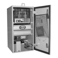
4. Disconnect the ribbon wire assembly from the prima-
ry connector board by lifting the locking tabs on either
side and pulling out the connector.
5. Use a flat-head screwdriver to loosen the five captive
screws on the primary connector board.
6. Holding the middle two screws on the primary con-
nector board, firmly pull the primary connector board
outward working left to right so as not to bend pins.
Removal/Replacement of CPU Board
1. Remove CPU board. Refer to Form 6 Recloser
Control Disassembly Instructions section.
2. Remove the TB1 terminal block strip from the back of
the module (Figure 2).
3. Carefully pull CPU board outward so as not to dam-
age the capacitor or any of the electrical components
on the Bezel tabs (Figure 6).
4. Proceed as appropriate for kit contents:
• If mounting plate is included with the kit proceed to
step 5.
• If mounting plate is not included with the kit contin-
ue with this step.
A. Unscrew the five captive screws on top of the
CPU board to release it from the mounting
plate.
B. Flip the mounting plate over and remove the two
mounting screws from the bottom of the mount-
ing plate.
C. Lift the CPU from the mounting plate.
D. Install new CPU onto mounting plate and
replace the five captive screws.
E. Flip mounting plate over and replace the mount-
ing screws on the bottom of the mounting plate.
5. If a new back plate is included with the kit, unscrew
the six back plate screws using a Phillips-head
screwdriver and replace the back plate (Figure 5).
6. Slide mounting plate into card guide and carefully line
up terminal strip to opening on the back plate.
7. Replace all of the terminal block strips.
8. Attach the new back plate over the communications
port on the back panel using two screws and washers
provided with kit.
9. Configure communications board with applicable
switches and program as necessary.
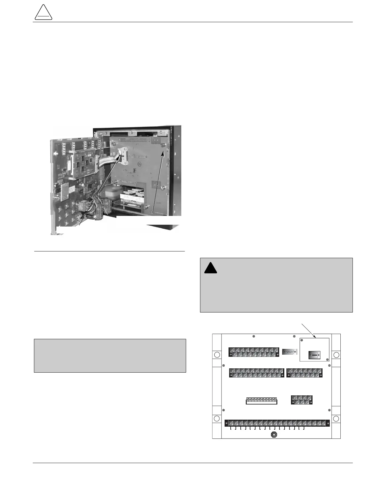
S280-70-11
5
Figure 5.
Form 6 control back plate.
CAUTION: Equipment misoperation. Do not
connect this control to an energized recloser until
all control settings have been properly programmed
and verified. Refer to the programming information for
this control. Failure to comply can result in control and
recloser misoperation, equipment damage, and per-
sonal injury. G110.3