Removal/Replacement of
Communications Accessory Board Only
The Form 6 control is equipped with a Communication
Board Accessory (expansion bay) offering versatile sup-
port for modern communication media. Seven distinct
communication options are available, providing two-way,
real time digital communications with a remote terminal
unit (RTU), wireless, telephone modem, Ethernet net-
work, or other communication devices. The following
options are available:
• No auxiliary communication card installed (standard)
• RS485 (isolated) Serial Communication Card (KME6-
3839-1S)
• Fiber-optic-based Serial Communication Card (ST)
(KME6-3839-2S)
• 10/100 Base-T dual Ethernet Communication Card
(2*RJ-45) (KME6-3839-5S)
• 100 Base-FX dual Ethernet Communication Card
(2*MT-RJ) (KME6-3839-3S)
• 10/100 Base-T, 100 Base-FX Ethernet
Communication Card (RJ-45 + MT-RJ) Multi-mode
(KME6-3839-4S)
• 100 Base FX dual Ethernet Communication Card (2
SC) Single-Mode (KME6-3839-6S)
Additional accessories are being continuously devel-
oped. Contact your Cooper Power Systems representa-
tive for the latest information regarding particular media
and communication protocol support.
Note: Form 6 Rack Mount Controls with serial numbers below
20,000 and Form 6 Pole and Yard Mount Controls with
serial numbers below 10,000 will need an additional
CPU replacement kit to upgrade a communications
board. Refer to KME6-3837-3S (pole mount) or KME6-
3837-4S (rack/yard mount).
This procedure will be used when changing communica-
tions accessory board:
1. Remove the CPU circuit board. Refer to Form 6
Removal/Replacement of CPU Board section.
2. Remove the TB1 terminal block strip from the back of
the module (Figure 2).
3. Carefully pull the CPU board outward so as not to
damage the capacitor or any of the electrical compo-
nents on the Bezel tabs (Figure 6).
4. Install two standoffs with copper washers into the
holes on the left side of the CPU board (Figure 7).
5. Carefully install the communication board onto the
CPU board so as to not bend any connections.
6. Install two screws with lock washers onto the com-
munications board.
Note: Use 10 in-lbs. of torque. Do not overtighten
standoffs.
Form 6 Recloser Control Disassembly, Reassembly, and Testing Instructions
6
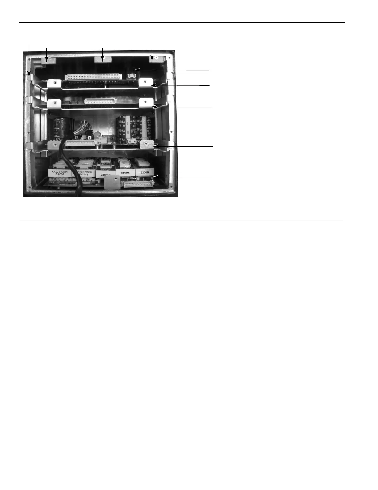
Figure 6.
Internal view of the Form 6 pole mount recloser control module.
CPU and Communications Board
Input/Output Board
Power Supply and RIF Board
Analog Board
Capacitor
Bezel Tabs
Shield Tabs