Form 6 Recloser Control Testing
Instructions
These instructions describe the testing of the Form 6
recloser control.
Communication Ports
Verify that the communication settings have been appropri-
ately configured for your selected communication protocol.
For information on configuring communications refer to
the appropriate instructions:
• S280-70-4 Form 6 Control Programming Guide
• S280-70-9 Form 6 Triple-Single Control
Programming Guide
Contact Input/Outputs
Standard Default Supervisory Input
Control and Output Status Contacts
Test inputs/outputs by asserting appropriate alarms per
the ProView™ software to verify that all contact outputs
operate (open and close). Figures 8 and 9 show the loca-
tion of the controls module manufacturing numbers.
Refer to Tables 2 and 3 for Operating Voltage
Requirements for Standard and Optional Supervisory
Inputs.
For information on testing refer to the appropriate
instructions:
• Service Information S280-70-1 Form 6 Rack Mount
Control Installation and Operation Instructions
• Service Information S280-70-2 Form 6 Yard Mount
Control Installation and Operation Instructions
• Service Information S280-70-3 Form 6 Pole Mount
Control Installation and Operation Instructions
• Service Information S280-70-7 Form 6 Triple-Single
Pole Mount Control Installation and Operation
Instructions
Form 6 Recloser Control Disassembly, Reassembly, and Testing Instructions
10
TESTING
CAUTION: Equipment damage; misoperation.
External leads must be shielded and the shield must be
grounded at both ends. Terminate each lead with a 320
Vac, 160 Joules metal oxide resistor (MOV), or equiva-
lent, at the remote end. Attach MOVs between the
leads and ground. Failure to properly shield and protect
leads can result in equipment damage and/or uninten-
tional operation. G117.3
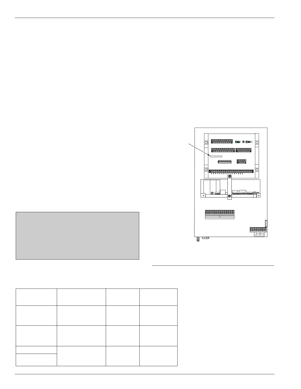
Figure 8.
Module Mfg. No. location on back of Form 6 pole
mount control.
Mfg. No. 6A0016010XX
Module Mfg. No.
Minimum
Module Nominal Operating
Mfg. No.* Input Voltage Current Time
6A00160101 12 Vdc – 48 Vdc 5 mA 5 milliseconds
through
6A00160104
6A00160105 48 Vdc – 125 Vdc, 5 mA 5 milliseconds
through 120 Vac
6A00160108
6A00160161 12 Vdc – 250 Vdc, 5 mA 5 milliseconds
6A00160160 120 Vac-240 Vac
(Triple-Single)
TABLE 2
Operating Voltage Requirements for Standard and Optional
Supervisory Inputs for Form 6 Pole Mount Recloser Control
Refer to Figure 6 for location of Module Mfg. No.