7. Slide mounting plate into card guide and carefully
push the assembly into the module.
8. Replace the TB1 terminal block strip.
9. Attach fiber/wire cover plate over the communications
port on the back panel using two screws and washers.
10. Configure communications board with applicable
switches, and program as necessary.
Removal/Replacement of I/O Board
1. Remove the I/O circuit board. Refer to Form 6
Recloser Control Disassembly Instructions section.
2. Remove the TB3 and TB4 terminal block strips or
cover plate from the back of the control module
(Figure 2).
3. Carefully pull I/O board outward so as not to damage
any of the electrical components.
4. Unscrew the five screws on top of the I/O board using
a Phillips-head screwdriver to release it from the
mounting plate.
5. Lift I/O board from shield.
6. Install new I/O board onto mounting plate and replace
the five screws.
7. Slide mounting plate into card guide and carefully line
up terminal strip to opening on the back plate.
8. Replace the TB3 and TB4 terminal block strips.
Removal/Replacement of Power Supply
or Recloser Interface Board (RIF)
Note: The Form 6 pole mount control will not contain an inter-
nal power supply board.
1. Remove the power supply or RIF circuit board. Refer
to Form 6 Recloser Control Disassembly
Instructions section.
2. Remove the TB5 and TB6 terminal block strips from
back of the control module (Figure 2).
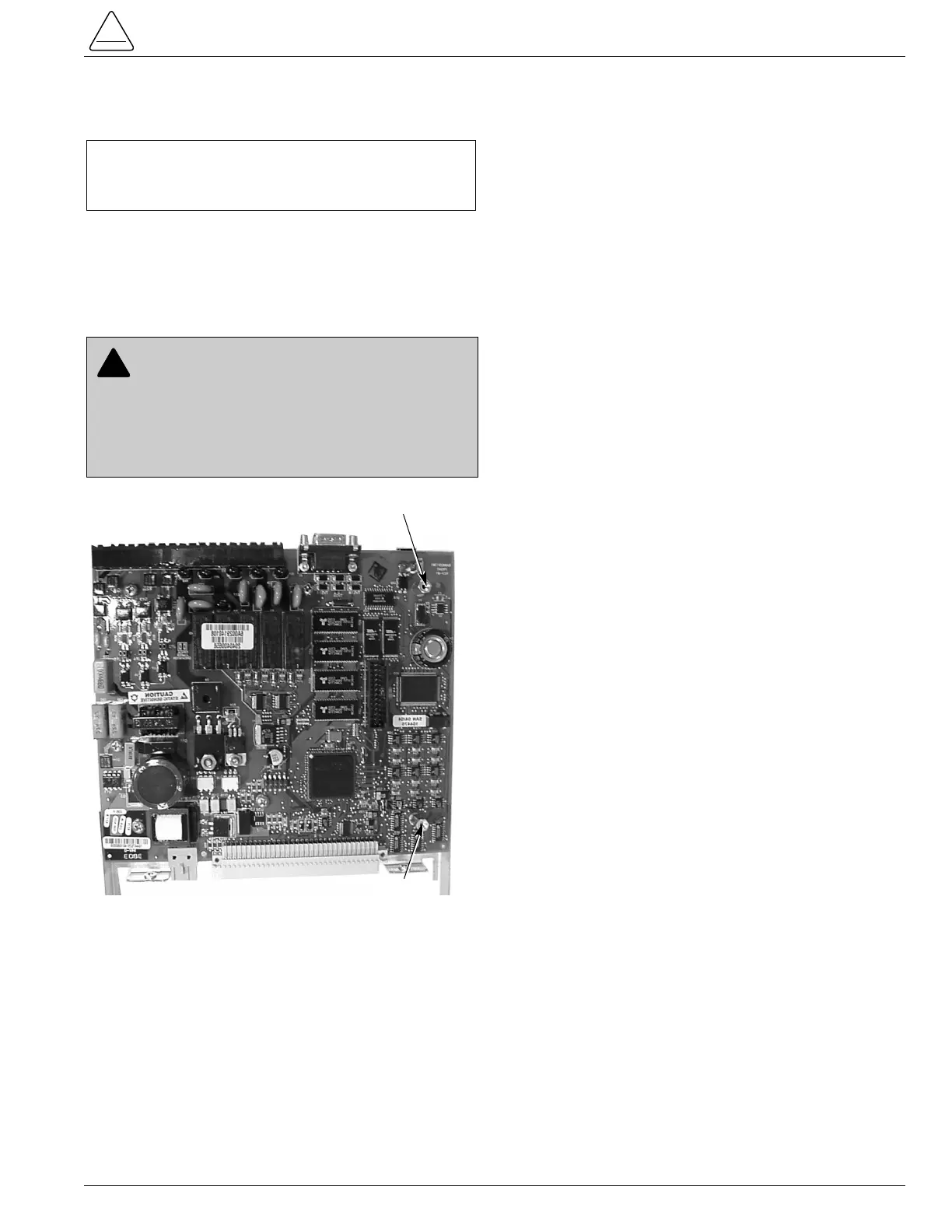
3. Carefully pull power supply and RIF board mounting
plate outward (Figure 4). Disconnect wire assembly
from the display assembly.
4. Unscrew the four screws on top of the power supply
or RIF board using a Phillips-head screwdriver.
5. Lift power supply board off of mounting plate and
carefully separate the board to board connector
between the RIF and the power supply board.
6. Install new power supply board onto mounting plate
and replace the four screws.
7. Slide mounting plate into card guide and carefully line
up terminal block strip to opening on the back plate.
8. Replace the TB5 and TB6 terminal block strips.
S280-70-11
7
CAUTION: Equipment misoperation. Do not
connect this control to an energized recloser until
all control settings have been properly programmed
and verified. Refer to the programming information for
this control. Failure to comply can result in control and
recloser misoperation, equipment damage, and per-
sonal injury. G110.3