Form 6 Recloser Control
Disassembly Instructions
These instructions describe the disassembly of the Form
6 recloser control.
1. Remove the Form 6 Control from Service. Refer to
appropriate Service Information Instructions:
• Service Information S280-70-1 Form 6 Rack Mount
Control Installation and Operation Instructions
Remove the Control from Service section
• Service Information S280-70-2 Form 6 Yard Mount
Control Installation and Operation Instructions
Remove the Control from Service section
• Service Information S280-70-3 Form 6 Pole Mount
Control Installation and Operation Instructions
Remove the Control from Service section
• Service Information S280-70-7 Form 6 Triple
Single Pole Mount Control Installation and
Operation Instructions Remove the Control from
Service section
2. Carefully transport the recloser control to a suitable
service facility.
Note: The entire disassembly, reassembly, and testing
process should be conducted in a clean environ-
ment, such as a repair shop.
This step applies to Form 6 Pole and Yard mount controls.
3. Remove module from cabinet as applicable.
A. For complete scheme structure and verification
refer to appropriate instructions:
• Service Information S280-70-4 Form 6 Control
Schemes section
• Service Information S280-70-9 Form 6-TS
Control Schemes section
B. Disconnect SCADA communications to the Form 6
control.
C. Remove all applicable connecting wires from
module.
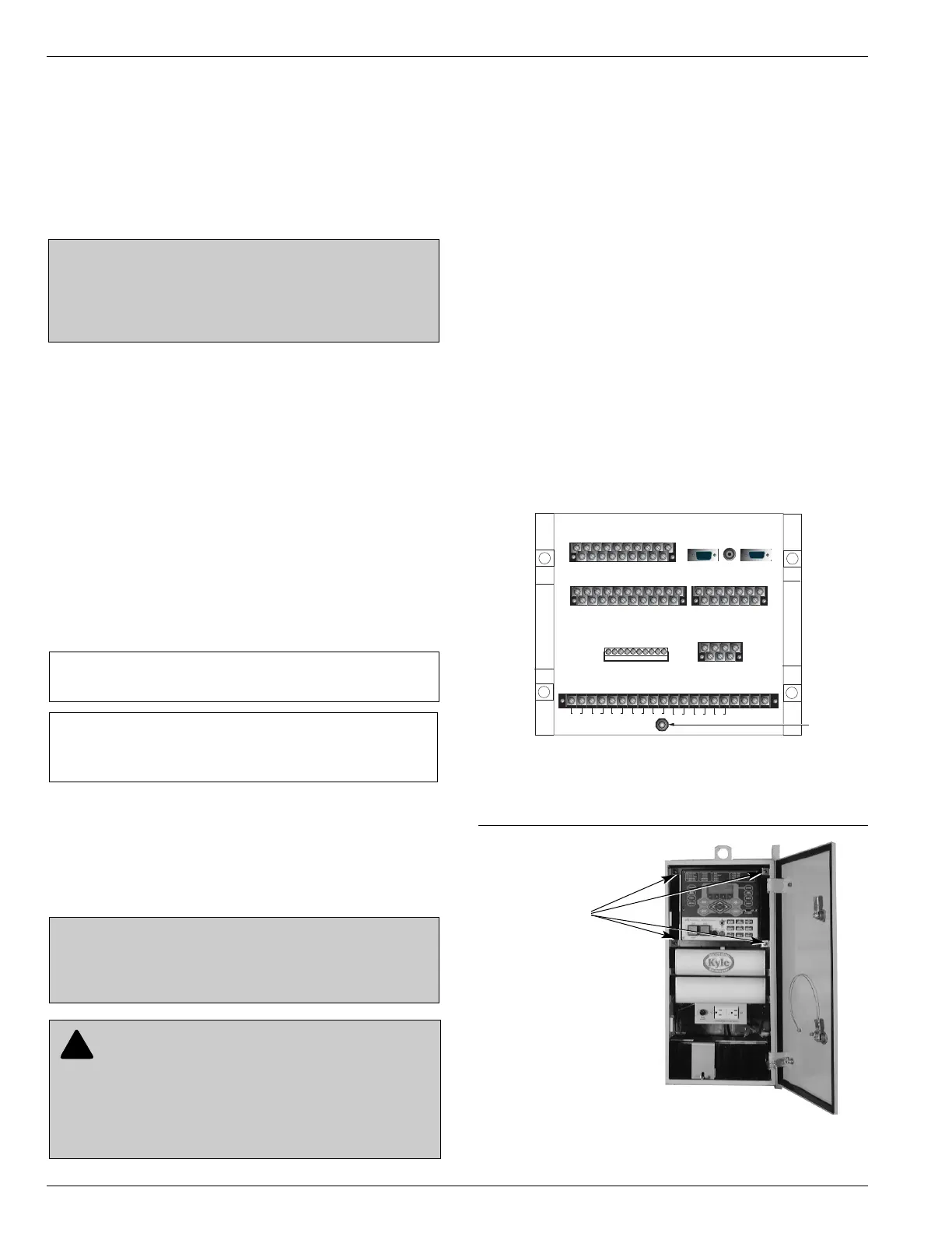
D. Remove the 7/16 inch grounding nut and lock-
washers located on the bottom of the control mod-
ule (Figure 2).
E. Remove the four mounting nuts that secure the
front of the module to the cabinet (Figure 3).
Form 6 Recloser Control Disassembly, Reassembly, and Testing Instructions
4
DISASSEMBLY
CAUTION: Recloser misoperation. The control must
be removed from service prior to performing any main-
tenance, testing, or programming changes. Failure to
comply can result in misoperation (unintentional oper-
ation) of the recloser. T216.2
IMPORTANT: Isolate all power connections to the
Form 6 recloser control, i.e., AC voltage sensing and
SCADA, before removing control from service.
IMPORTANT: Make sure the power is turned off and
the battery is disconnected.
CAUTION: Equipment damage. Always wear a
grounding wrist strap to control static electricity before
handling circuit boards. Failure to use this strap may
result in circuit board damage.
T253.1
Figure 2.
Location of grounding nut and lockwashers on the
rear panel of the Form 6 pole mount control (below
SN 10000).
CAUTION: Recloser misoperation. Before
downloading configuration files or settings to the
equipment, verify that the files and settings are correct
for the location and application. Downloading configu-
ration files or settings designed for a different location
or application can result in severe personal injury and
equipment damage. G133.0