English
Operating instructions
9
THE ELECTRICAL SAFETY OF THIS AUTOMATIC CREAM-WHIPPER IS
REACHED ONLY WHEN THE SAME IS CORRECTLY CONNECTED, BY
QUALIFIED AND CERTIFIED PERSONNEL, TO AN EFFICIENT EARTH-
ING SYSTEM, MADE AS PROVIDED FOR IN FORCE SAFETY REGULA-
TIONS.
The manufacturer must not be considered responsible for eventual damages
caused by an inadequate electric plant or earthing.
All the device’s electrical features required for the system’s proportioning are reported
on the Technical Data Plate and on the Technical Handbook.
FOR THE PREPARATION OF THE ELECTRICAL PLANT WHICH SUPPLIES THE DEVICE, IT IS COMPUL-
SORY TO FOLLOW THE PRESCRIPTIVE STANDARDS IN FORCE. IN PARTICULAR:
- The electrical capacity of the plant must exactly match the supply’s voltage and frequency required by the device;
- the current capacity of the plant must be suitable for the device’s input;
- the plant must end with an accepted 5 pole (380V-415V-3~), or 4 pole (200V-220V-3~), or 3 pole (220V-1~), electrical
socket and with electrical and mechanical suitable characteristics. The electrical socket’s poles must be marked with
appropriate letters (phases R-S-T + neutral N + earth); the earth’s pole must be recognizable;
- The electrical socket must prevent, through appropriate mechanical measures, the plug’s wrong connection;
- the electrical socket must have, above or annexed, a breaker, conformed to the in force safety laws, with an associated
gearing positioned near the device, in a place easily reachable by the operator. It must also be protected by fuses,
above or annexed, with characteristics suited at the current absorbed by the device.
A WRONG CONNECTION ON THE EARTH TERMINAL MAY CAUSE SERIOUS DANGER.
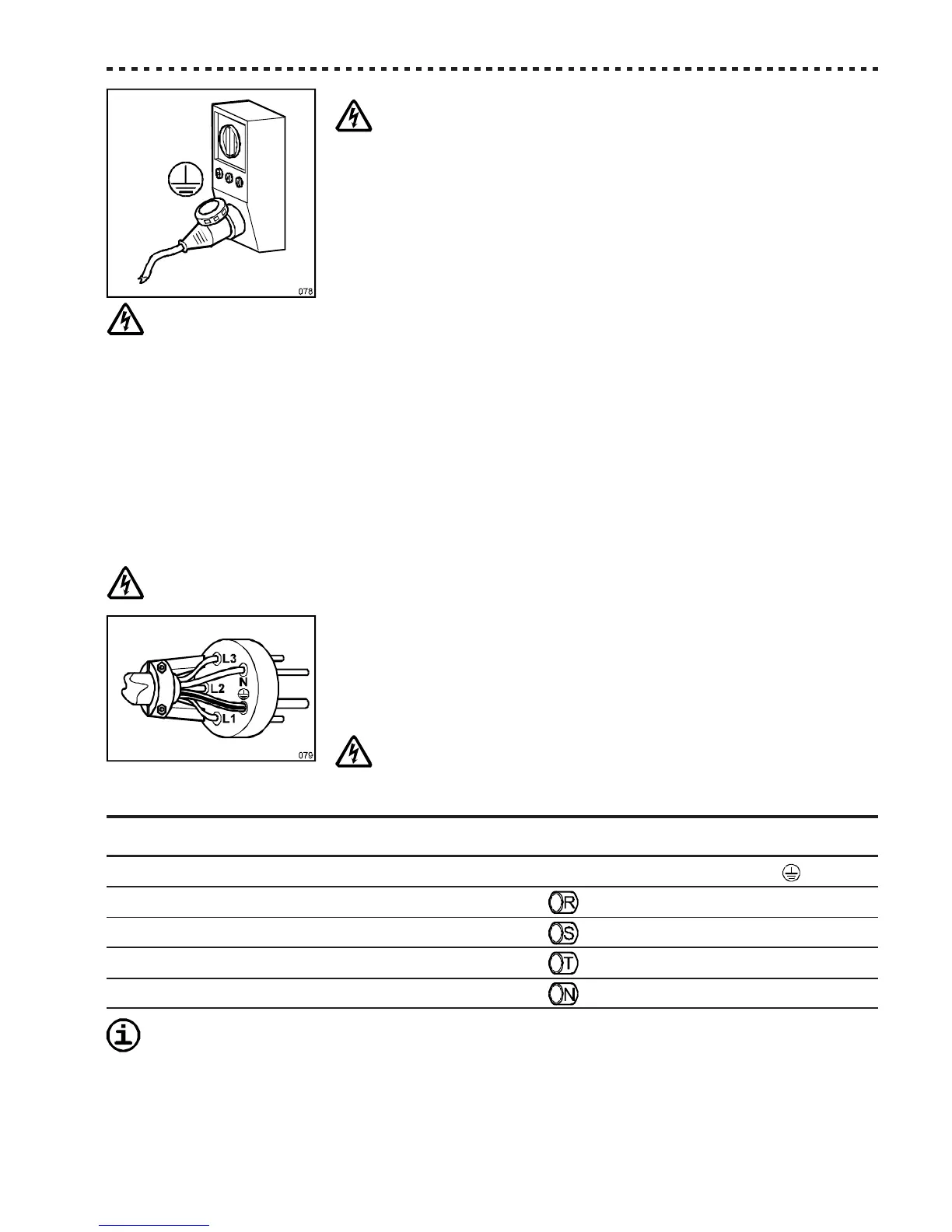
A 5 pole (380V-415V-3~), or 4 pole (200V-220V-3~), or 3 pole (220V-1~) plug, suit-
able with the current socket, must be installed at the end of the device's power supply
cable.
The device’s power supply cable is composed by 5 or 4 or 3 coloured wires, and
eventually marked with appropriate bands, which must be connected to the relevant
plug’s terminals, as shown in the following table.
A WRONG CONNECTION IN THE PLUG’S INSIDE MAY CAUSE SERI-
OUS DANGER. FOR THE CONNECTION, ONLY ADDRESS YOURSELVES
TO QUALIFIED AND AUTHORIZED TECHNICIANS.
Kind Wire Wire Code marked near
of supply colour marking band plug’s terminal
EARTH GREEN/YELLOW None PE or
Phase R BLACK R or L1
Phase S BROWN S or L2
Phase T BLACK T or L3
NEUTRAL BRIGHT or SKY BLUE N
Before using the device it is necessary to:
- connect it to the water network, if the device features a water condensator (Ref. Par. 5.4);
- carry out the initial functioning check (Ref. Par. 5.5).