HD 1300 / HD 1300 A Operator Manual 89
EN
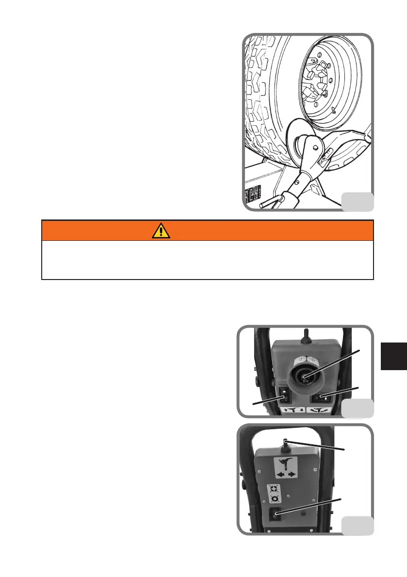
4. A rubber guard fit on the tool arm (case with
tools) prevents crushing between the tool arm
(case with tools) and the base.
NOTE
When working on rims with small diameters, remove
the tool unit and position it in the second coupling
hole (fig.13). This optimises the position of the tool
unit with the centre of the turntable.
To prevent accidents when using the included or optional accessories, make sure
that the mechanical parts have been correctly installed and well fixed to the parts.
When working, firmly grip the manual accessories.
CAUTION!
DESCRIPTION OF THE MOBILE UNIT CONTROLS (STANDARD
VERSION)
- Four-position lever (P, Fig.14) that: uses a
horizontal movement to control the turntable
spindle support carriage; uses a vertical movement
to control the upward/downward movement of the
turntable spindle support arm.
- The three-position button (central zero) (O, fig.
14) controls the lifting and lowering of the tool
support arm (version HD1300A / AR only)
- The three-position button (central zero) (Q, fig.
14) controls the right and left rotation of the tool
support arm (version HD1300A / AR only)
- The three-position lever (central zero) (S, fig.
15) that controls the right and left translation of
the tool support arm.
- The three-position lever (central zero) (R, fig.15)
that controls spindle opening and closing.
13
O
P
Q
14
R
15
S




 To Next Page