EasyManua.ls Logo

CORNING Everon 6200 User Manual

CORNING Everon 6200
53 pages
To Next Page IconTo Next Page
Page #1 background imageLoading...
Page #1 background image
Corning Optical Communications
User Manual
| E62-H2
|
Page 1
1.
2.
GENERAL INFORMATION
The E62-H2RU is a high-power remote unit supporting cellular technologies on fiber optic
cable using the CPRI protocol. The H2 is ideal for multioperator multiband deployments of
cellular services in large coverage areas. The H2 supports up to 43 dBm output per band in
single 2T2R or dual 1T1R up to 80 MHz per band. The H2 converts an optical signal to RF
and then transmits at the relevant 3GPP band and receives the analog RF signal, conditions
it, and converts it back to optical for routing to the E2 or A2.
High-Power (E62-H2)
User Manual
Everon™ 6200
This document describes the installation procedure for the E62-H2 unit.
This is NOT a CONSUMER device. It is designed for installation by FCC LICENSEES and
QUALIFIED INSTALLERS. You MUST have an FCC LICENSE or express consent of an FCC
License to operate this device. NOTE: Only authorized person can enter the area where the
antenna is installed. And the person is fully aware of the potential for exposure and can exercise
control over his or her exposure by leaving the area or by some other appropriate means.
Awareness of the potential for RF exposure in a workplace or similar environment can be provided
through specific training as part of a RF safety program.
Question and Answer IconNeed help?

Do you have a question about the CORNING Everon 6200 and is the answer not in the manual?

CORNING Everon 6200 Specifications

General IconGeneral
BrandCORNING
ModelEveron 6200
CategoryPortable Generator
LanguageEnglish

Summary

General Information

Safety Information

Safety Instructions

Covers all safety precautions for installation, operation, and maintenance of the Everon 6200 system, including electrical hazards and RF exposure.

Site and Environmental Setup

Site Considerations

Details FCC RF exposure limits, system delay considerations, and ideal installation locations for convenience.

Environmental Considerations

Specifies operating humidity (85%) and temperature ranges (-10°C to +50°C) for optimal system reliability.

DC Power Connections

Illustrates DC power cable connections for AU/EU and HPRU units, specifying wire gauge and polarity.

Warning Marks

Installation Preparation

Unpacking and Inspecting

Outlines procedures for receiving, inspecting packing containers, unpacking, and verifying shipment contents.

Device Inspection and Site Planning

Inspecting the Device

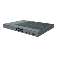
Provides a checklist for inspecting the device's appearance, dimensions, and component integrity after unpacking.

Site Investigation

Guides site assessment for suitability, including environmental factors, power sources, and signal quality.

Installation Tools

Lists the necessary equipment and tools for installation, such as electric percussion drills and screwdrivers.

Torque Settings

Specifies torque values for different screw sizes (M3, M6, M10) required during installation.

Clearance

Defines required mounting clearances for convection and fan cooling in 19-inch racks/cabinets.

Installing the Access Unit (AU)

Accessories List

Lists all accessories included for the installation of the Access Unit (AU), such as screws, loops, and cables.

AU Rack Installation

AU Fan Installation

AU Wall Installation

AU Mounting Dimension Spacing

RF Connection for AU

Installing the Expansion Unit (EU-O)

Accessories List

Lists all accessories included for the installation of the Expansion Unit (EU-O), such as screws, loops, and cables.

EU-O Rack Installation

EU-O Wall Installation

EU-O Mounting Dimension Spacing

Installing the High-Power Remote Unit (H2RU)

Accessories List

Lists all accessories included for the installation of the High-Power Remote Unit (H2RU), including fasteners and brackets.

H2RU Wall Installation (Back on the Wall)

H2RU Wall Installation (Side on the Wall)

H2RU Pole Installation

H2RU Mounting Dimension Spacing

Optical Connection

Optical Transceiver Module

Explains single-port bidirectional and dual-port SFP transceivers, their wavelengths, and LED indicator functions.

AU Optical Port Description

EU-O Optical Port Description

RU Optical Port Description