Inspecting the Device
After unpacking the device, place the device on solid ground and check the following to ensure the device has not been
damaged:
1.
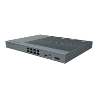
Inspect the device’s appearance, overall dimensions, and weight.
2.
Check that the device has not been deformed or bent in any way.
3.
Check that there are no warps, scratches, bubbles, or dirt marks.
4.
Check that there are no loose, missing or incorrectly fastened screws.
5.
Check that the installation slots in the cabinet sub-rack are rectangular.
6.
Ensure that the guide bar has not been damaged and the fittings and auxiliary parts are intact.
7.
Check that the silk-screened images on the device are visible and intact.
Installation Preparation
Site Investigation
Before installation, the installer should contact the project director to ensure that the site is suitable for installation.
Details required include information about the installation site, such as whether there is an iron tower or high mast
nearby, the surrounding environmental conditions such as temperature and humidity, the power source, and so on.
Installation staff should complete a site investigation with the project director before construction and conduct field
observation of the installation site and the coverage area of the device, to confirm factors such as signal intensity, signal
quality, the required coverage range, device location, antenna-feeder system, and power supply system.
Note: Only maintenance personnel or users who understand the reason for access, are experienced with restricted area
access, and understand the necessary preventive measures should access the installation site.
Installation Tools
The following equipment and tools are required for a successful installation:
Electric percussion drill / Screwdriver / Wrench
Torque Settings
Clearance
You must ensure the following mounting clearances for mounting within a 19-inch rack/cabinet:
Convection cooling:
Maintain 3U clearance between the bottom of the device and any other.
Maintain 3U clearance from the top surface of the device to the top of the rack.
Fan Cooling:
You can mount the fan between the bottom of the device and any other.
Maintain 2U clearance between the bottom of the device and any other.