3C Interfacing and Programming CPI Canada Inc.
Use and disclosure is subject to the restrictions on the title page of this CPI document.
Page 3C-6 CMP 200
X-Ray Generator Service Manual Ch # 901476-04 Rev. C
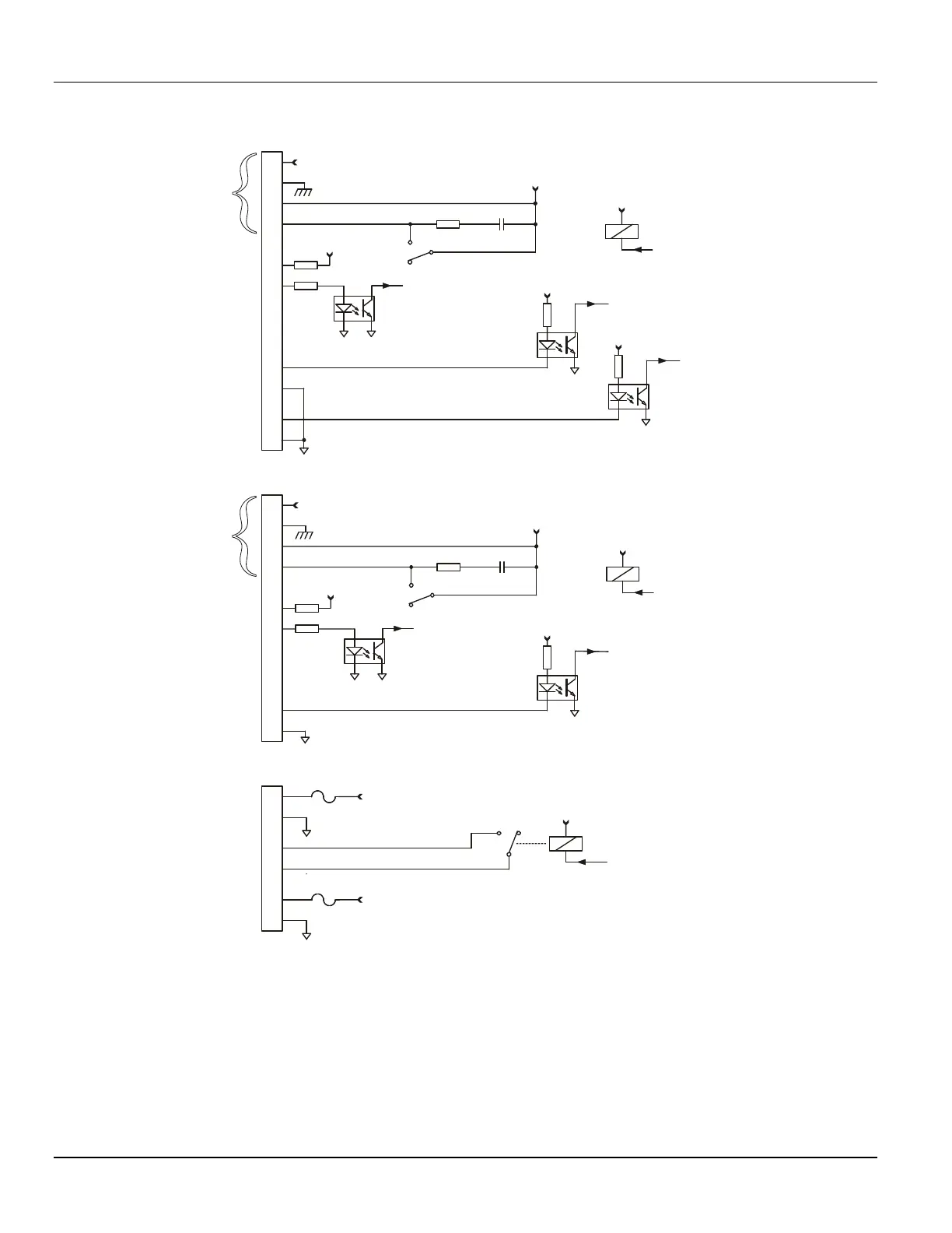
3C.2.3 Inputs & Outputs (simplified schematic)
10
6
3
4
10
BUCKY RETURN
FROM 24 VAC
SOURCE
FROM 24 VDC
SOURCE
BUCKY RETURN
+24 VDC
+24 VDC
+24 VDC
+24 VDC
+24 VDC
+12 VDC
+12 VDC
BUCKY 1 START
BUCKY 2 START
BUCKY 1 START
COMMAND
BUCKY 2 START
COMMAND
BUCKY 1 READY
BUCKY 2 READY
DOOR INTERLOCK
INTERLOCK 1
INTERLOCK 2
** 24 VDC
110 / 220 VAC
BUCKY 1
OUTPUTS
TOMO / BUCKY 2
OUTPUTS
INTERLOCK
#1 *
BUCKY 1
READY *
BUCKY 2
READY *
INTERLOCK #2 /
TOMO EXPOSURE
INPUT *
DOOR
INTERLOCK *
24 VAC OUT
FOR COLLIMATOR
LAMP
ROOM
LIGHTS
24 VDC OUT
FOR TUBE
STAND LOCKS
J2
J4
J11
9
5
4
3
9
8
2
2
4
7
1
1
3
6
6
2
5
5
1
FILE: CMP200
012B.CDR
+
*
REFER TO TABLE 3C-1 FOR REQUIRED INPUT LOGIC LEVELS
F11
F12
K1
K1
K3
K3
C3R2
C10R15
** 24 VDC
110 / 220 VAC
+12 VDC
ROOM LIGHT
“ON” COMMAND
K7
**
THE BUCKY OUTPUTS MAY BE CONFIGURED FOR +24 VDC, 110 VAC,
OR 220 VAC. REFER TO CHAPTER 8 FOR DETAILS.
Figure 3C-1: J2, J4, and J11 inputs and outputs (H.V. auxiliary board)


 To Next Page