CPI Canada Inc. Interfacing and Programming 3C
Use and disclosure is subject to the restrictions on the title page of this CPI document.
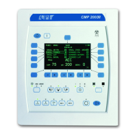
CMP 200
X-Ray Generator Service Manual Ch # 901476-04 Rev. C Page 3C-7
3C.2.4 AEC Interconnect
Refer to chapter 3D for an overview of AEC theory, for AEC chamber connections, and for the AEC
calibration
procedure.
3C.2.5
DR imaging system
CMP 200 DR X-ray generators are factory-configured to
interface with one or more DR imaging systems.
Refer to the compatibility statement in chapter 1 to determine which DR imaging
system(s) this model of
generator is compatible with. The DR imaging system is connected to 37-pin “D” connector J25 on the
generator control board. The corresponding digital imaging supplement will be included in the front of this
manual. Refer to that supplement for the installation and setup procedure of the DR imaging system.
3C.3.0 GENERATOR PROGRAMMING
If you are using a membrane console, the generator
may
be programmed and calibrated via the control
console or via PC GenWare. When using the console for programming and calibration, all programming /
calibration menus are displayed on the LCD display window on the console. The “soft key” buttons on the
console are used to navigate through the programming screens and to select and enter values in this section.
When using the touchscreen console, the generator must be programmed and calibrated via
Touchscreen GenWare. This requires the GenWare utility software, which can be accessed via the
GenWare button in the System Utilities menu. Alternately, PC GenWare may be used to program the
generator if desired.
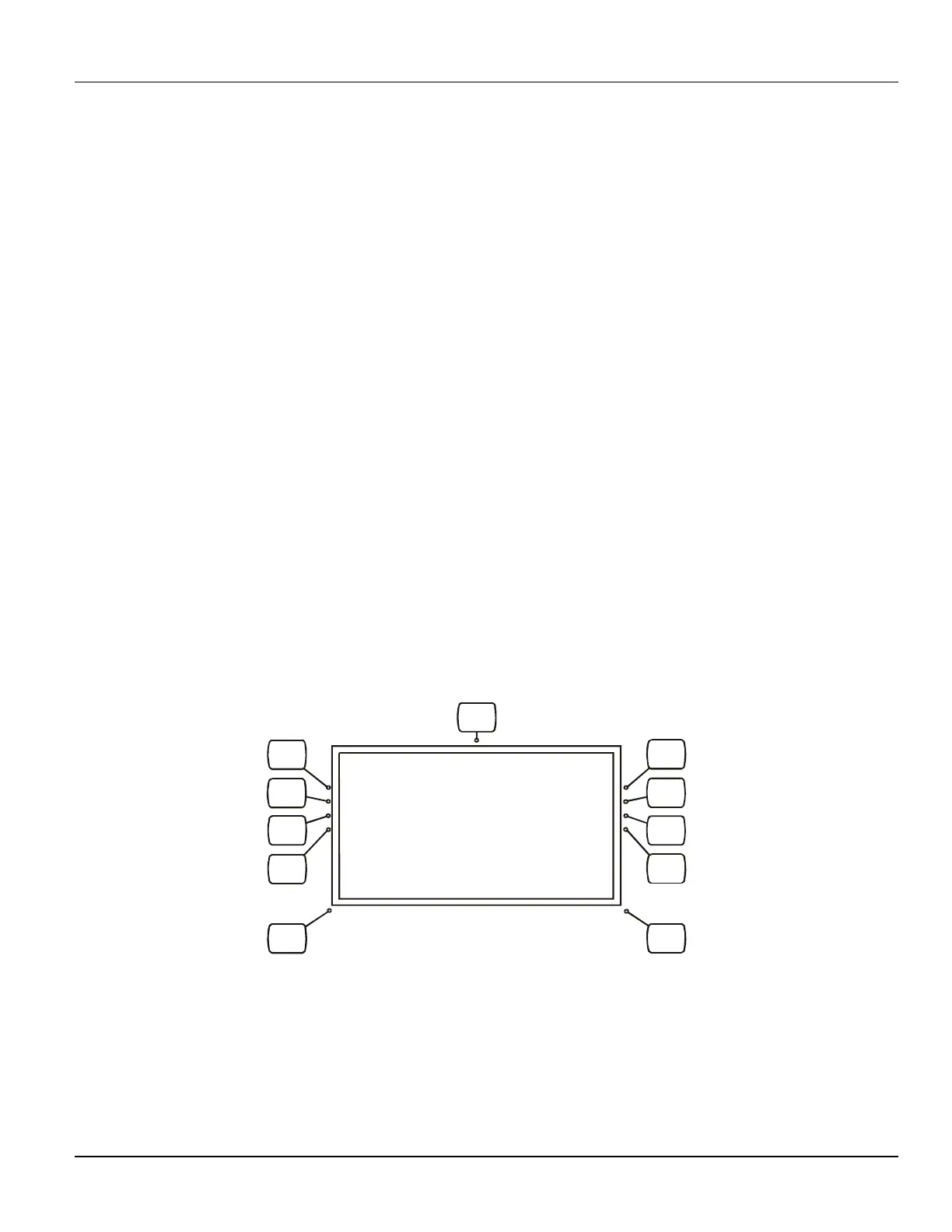
3C.3.1 Entering Into Programming Mode
To enter into the programming mode if using the membrane console, follow the steps below.
IND100R_006A.CDR
1
4
5
2
MENU
BACK
FORWARD
3
6
7
8
Figure 3C-2: Programming / calibration mode reference
 Loading...