EasyManua.ls Logo

Craftsman 113.198210 User Manual

Craftsman 113.198210
68 pages
To Next Page IconTo Next Page
Page #1 background imageLoading...
Page #1 background image
Save This Manual
For Future Reference
I 0" ELECTRONIC
RADIALSAWWITH
23" CABINETAND
1 DOOR
S_rial
Number ...........
Model and s_rial numbers
may b_ found on the
backside of the base
You should record both
model and s_rial number in
a place for future us_,
CAUTION:
READALL
INSTRUCTIONS
CAREFULLY
I
® assembly
® operating
repair parts
Sold by SEARS,ROEBUCKAND CO., Chicago, IL 60684 U.S.A.
Part No, SP5016 Printed in US.A.

Table of Contents

Question and Answer IconNeed help?

Do you have a question about the Craftsman 113.198210 and is the answer not in the manual?

Craftsman 113.198210 Specifications

General IconGeneral
TypeTable Saw
Model Number113.198210
Blade Diameter10 inches
Motor Power1.5 HP
Voltage120V
Arbor Size5/8 inches
Amps15 amps

Summary

Craftsman 10-Inch Electronic Radial Saw Owner's Manual

General Power Tool Safety Instructions

Tool Familiarity and Safe Operation

Understand your tool, keep it clean, use correct tools, and avoid forcing.

Work Area and Personal Safety

Maintain clean area, avoid hazards, keep children away, wear safety goggles and apparel.

Additional Radial Saw Safety Instructions

Before Using the Saw

Complete assembly, review safety, and check equipment before operation.

Pre-Operation Checks

Plan work, check for damaged parts, and ensure proper setup before each use.

Eye Protection Requirement

Electrical Connections and Power Supply

Wiring and Grounding Safety

Highlights hazards of improper grounding, worn cords, and recommends circuit protection.

Assembly and Alignment Guide

Framing Square Accuracy Check

Instructions for checking the accuracy of a framing square.

Unpacking and Preassembly Steps

Preassembly Safety Warning

Crucial warning against plugging in the power cord before assembly is complete.

Checking Package Contents

Loose Parts List Details

Detailed list of loose parts organized by bags for Model 113.198210.

23-Inch Cabinet Assembly Guide

Cabinet Squareness and Leveling Procedure

Checking Cabinet Squareness

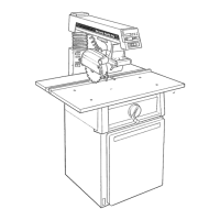
Using a framing square to ensure cabinet panels are aligned correctly.

Leveling Foot Adjustment

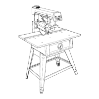
Adjusting leveling feet for stability and proper arm slope.

Door and Saw Unit Mounting

Saw Unit Mounting Steps

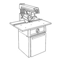
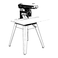
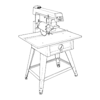
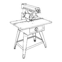
Securing the main saw unit onto the assembled cabinet.

Motor Mounting and Handwheel Attachment

Motor Mounting Procedure

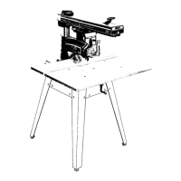
Instructions for mounting the motor, including initial preparations.

Alignment Procedure: Column and Table Channels

Column Tube Adjustment

Adjusting the column tube for smooth movement within its support.

Table Mounting Channel Installation

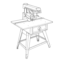
Attaching and leveling table support channels for table-to-arm parallelism.

Front Table Installation

Alignment: Squaring Crosscut Travel

Front Table Flatness Adjustment

Adjusting front table flatness using leveling screws.

Crosscut Travel Squareness

Aligning the blade to travel square to the rip fence.

Alignment: Squaring Blade to Table

Saw Blade to Table Squaring

Ensuring the saw blade is square to the work table.

Alignment: Squaring Blade to Rip Fence

Blade-to-Rip Fence Alignment

Aligning the blade parallel to the rip fence to prevent binding.

Bevel Heel Adjustment

Guard and Anti-Kickback Assembly Installation

Anti-Kickback/Spreader Adjustment

Adjusting the anti-kickback and spreader assembly for proper function.

Electronic Indicator System Functions

Battery Installation and Encoder Alignment

Miter Angle Encoder Alignment

Procedures to align the miter encoder for accurate angle readings.

Bevel Angle Encoder Alignment

Using the Electronic Indicator System

Setting Reference Points

Establishing zero reference points for bevel, miter, elevation, and rip positions.

Location and Function of Controls

Control Safety Warnings

Crucial safety warnings regarding switch locking and accessory shaft usage.

Power Switch and Key Operation

Blade Guard and Anti-Kickback Assembly

Anti-Kickback/Spreader Adjustment for Ripping

Adjusting the anti-kickback and spreader assembly for proper function.

Basic Saw Operation Guide

Ripping Operations: In-Ripping and Out-Ripping

Adjusting Lock Handles and Arm Column

Adjusting Carriage and Miter Lock Mechanisms

Troubleshooting Guide - General Practices

Troubleshooting Sequence Warning

Warning to follow alignment procedures sequentially for accurate results.

Troubleshooting Guide - Electronics

Troubleshooting Guide - Motor

Maintenance and Lubrication

Safety Precautions for Maintenance

Safety warnings to turn off power and remove plug before maintenance.

Related product manuals