i i illll, ii,i ii ,ll .... , ....................................
i/ J iui
MBLY
TO INSTALL THE UPPER HANDLE AND
CRANK ASSEMBLY
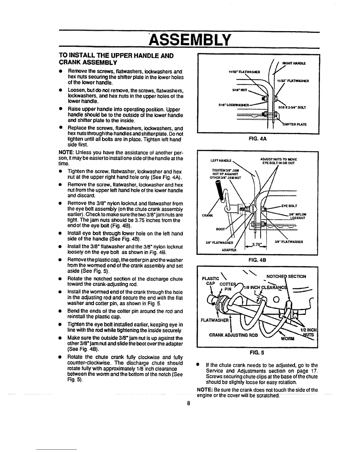
• Removethe screws,flatwashers,to.washers and
hexnutssecudngthe shifterplateinthe lowerholes
ofthelowerhandle..
• Loosen,t_Jtdonotremove,thescrews,flatwashers,
lockwashers, and hex nutsinthe upperholesof the
lowerhandle_
• Raiseupperhandle into operatingposition.,Upper
handleshouldbeto theoutsideof the lower handle
and shifterplate to the inside.
• Replacethe screws0flatwashers,lockwashers, and
hexnutsthroughthehandlesandshifterplate.Donot
lightenuntilallboltsare in ptace_T'_jhtenlefthand
sidefirst.
NOTE: Unless you have the assistanceof anotherper-
son,itmay beeasiertoinstallonesideofthehandleatthe
time.
• Tightenthe screw,flat'washer,Iockwasherand hex
nutat the upperdght hand holeonly (See Fig,4A),
• Removethe screw,flatwasher,Iockwasherandhex
nutfrom the upperlefthand holeofthe lowerhandle
and discard,
• Removethe 3/8" nyloniocknutand flatwasherfrom
theeye bolt assembly(onlhe chutecrankassembly
eadier)_Checktomakesurethetwo3/8"jamnutsare
tight.The jam nutsshouldbe3.75 inches fromthe
endofthe eye bolt (Fig. 4B).
• Installeye bolt throughlower hole on the left hand
sideof the handle(See Fig.,4B)_
• Installthe 3/8"ftatwasherandthe3/8"nylonlocknut
looselyon the eye bolt as showninFig_4Bo
• Removetheptasticcap,thecotterpinandthewasher
from the wormedend ofthe crankassemblyandset
aside (See Fig°5)_
• Rotate the notchedsectionof the dischargechute
towardthe crank*adjustingrod..
• Installthewormed endof thecrankthroughthehole
in the adjustingrod and securethe endwiththe flat
washer andcotterpin, as shownin Fig.5
• Bendthe ends of the cotter pin aroundthe rodand
reinstallthe plasticcap.
• Tighten the eye bolt installedearlier, keepingeye in
linewiththe rodwhiletighteningtheinsidesecurely
• Make surethe outside3/8"jam nutisupagainstthe
other3/8"jamnutandslidethebootovertheadapter
(See F_,.4B).
• Rotate the chute crank fully clockwiseand fully
counter-clockwise, The discharge chute should
rotatefullywith approximately 1/8 inchclearance
betweenthewormand the bottomofthenotch(See
Fig.5).
_'tB"
FIG. 4A
= _
FIG. 5
• If thechutecrankneedsto be adjusted, go to the
Service and Adjustments section on page 17_
Screwssecuringchuteclipsatthebaseofthechute
shouldbe slightlyloose for easyrotation.
NOTE: Besurethe crankdoes nottouchthe sideofthe
................................................. engineorthe coverwillbe scratched,:......................................................................
8