SERVICE AND ADJUSTMENTS
CAUTION: ALWAYS DISCONNECTTHE
SPARK PLUG WIRE AND TIE BACK
AWAY FROMTHE PLUG BEFORE MAK-
ING ANY ADJUSTMENTS OR REPAIRS.
TO ADJUST SKID HEIGHT
Thissnowthrowerisequippedwithtwo heightadjustment
skids,locatedon the outsideof the auger housing(See
Fig.20).These skidselevatethefront ofthesnowthrower.
For normalhardsudaces, adjustthe skids as follows:
• Check tirepressure(14to 17 pounds).See sideoftire
formaximuminflation.Donotexceed maximumpres-
sureon sideoftire.
• Place the extra shear boltssupplied(found in parts
bag) under eachend of thescraperbar near but not
underthe skid.
• Loosen the skid mountingnuts (See Fig. 20) and
adjustthe skids up to bring the front of the snow
throwerdown. Re-tightenthe mounting nuts.
• Set the skid on the othersideat the same height.
Forrockyoruneven surfaces,adjustthe skidsas follows:
• Raise the frontof the snowthrower by movingthe
skids down. This will help prevent rocks and other
debrisfrombeingpickedup andthrownbythe auger.
NOTE: Be surethatsnowthrowerissetat sameheighton
both sides.
TOADJUSTSCRAPER BAR
Afterconsiderableuse,the metalscraper bar willhave a
definitewear pattern. The scraperbar inconjunctionwith
theskidsshouldalwaysbeadjustedtoallow1/8"between
the scraperbar and the sidewalkor area to be cleaned.
The scraper bar may have to be returned to its original
lowersettingtomaintaintheoriginalperformancelevel.To
adjust:
• Positionthe snowthroweron a level sudace.
• Make sureboth tiresare equallyinflated.
• Loosen the carriage bolts and nuts securing the
scraperbar to the auger housing.
• Adjustthe scraper bar to the properposition.
• Tightenthecarriagebolts and nuts,making surethat
the scraperbar is parallelwiththe workingsurface.
For extended operation, the scraper bar may be
reversed. Ifthe scraper bar mustbe replaceddue to
wear,removethecarriage bolts andnutsandinstalla
newscraperbar.
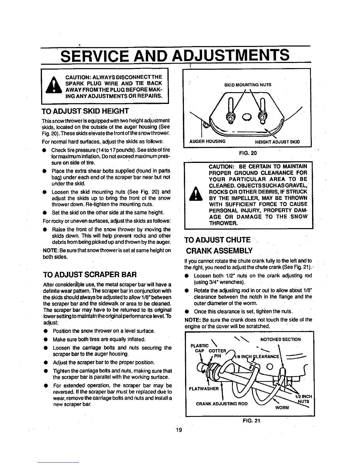
SKID MOUNTING NUTS
AUGER HOUSING
HEIGHTADJUSTSKID
FIG. 20
A
CAUTION: BE CERTAIN TO MAINTAIN
PROPER GROUND CLEARANCE FOR
YOUR PARTICULAR AREA TO BE
CLEARED. OBJECTSSUCH ASGRAVEL,
ROCKS OR OTHER DEBRIS, IF STRUCK
BY THE IMPELLER, MAY BE THROWN
WITH SUFFICIENT FORCE TO CAUSE
PERSONAL INJURY, PROPERTY DAM-
AGE OR DAMAGE TO THE SNOW
THROWER.
TO ADJUST CHUTE
CRANK ASSEMBLY
Ifyou cannot rotatethe chutecrankfully tothe leftandto
thedght,youneedto adjustthe chutecrank(See Fig.21).
• Loosen both 1/2" nuts on the crank adjustingrod
(using3/4" wrenches).
• Rotatethe adjustingrodin or outto allowabout 1/8"
clearancebetween the notch in the flange and the
outerdiameterofthe worm.
• Once thisclearance isset, tigtltenthe nuts.
NOTE: Be surethe crank does not touchthe sideofthe
engineor the coverwill be scratched.
_ NOTCHED SECTION
PLASTIC
CAP COTTER "_-
FLATWASHER
CRANK ADJUSTING ROD
WORM
1/2 INCH
FIG, 21
i9