SERVICE AND ADJUSTMENTS
TO ADJUST THE BELT GUIDES
There aretwo beltguidesonyoursnowthrower, a leftand
right.Afteryou replace the traction drivebelt, you need to
adjust one or both of the beltguides. Proceed as follows
for each bolt:
• Disconnectthe spark plugwire.
Removethe bolt cover (See Fig. 26).
Engagethe augerdrive clutchlever.
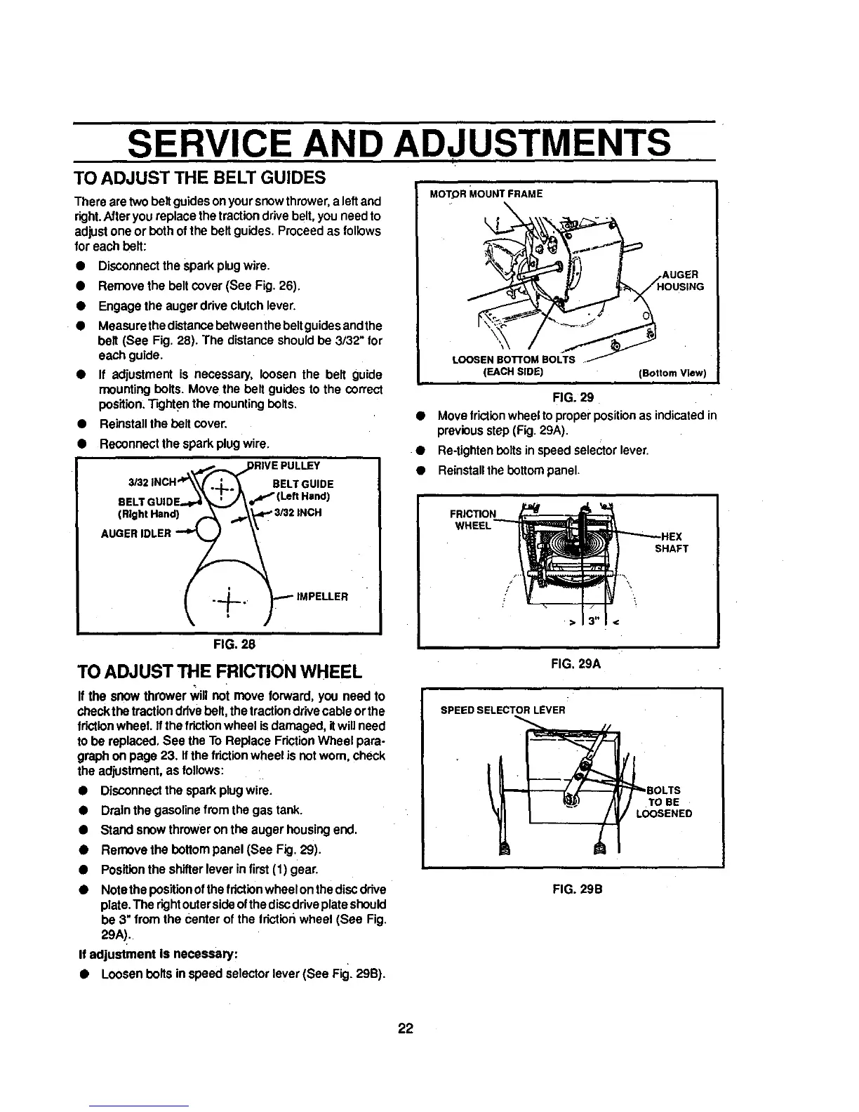
Measurethedistancebotween the beltguidesendthe
belt (See Fig. 28). The distance shouldbe 3/32" for
each guide.
• If adjustment is necessary, loosen the belt guide
mountingbolts. Move the belt guidesto the correct
position.Tightenthe mounting bolts.
• Reinstallthe bolt cover.
• Reconnectthe sparkplugwire.
eEL'
(Right Hand)
BELTGUIDE
FIG. 28
TO ADJUST THE FRICTION WHEEL
If the snow thrower _11 not move forward, you need to
check the tractionddvebolt, the tractiondrivecable orthe
frictionwheel. Ifthe frictionwheel is damaged, itwill need
to be replaced,See the To Replace FdctionWheel para-
graph on page 23. If the fdctionwheel is notworn, check
the adjustment,as follows:
• Disconnectthe sparkplugwire.
• Drainthe gasolinefrom the gas tank.
• Stand snow throweronthe auger housingend.
• Remove the bottompanel (See Fig. 29).
• Positionthe shitterlever in first(1) gear.
Notethe positionofthefdctionwheelon thediscdrive
plate,The dghtoutersideofthediscdriveplateshould
be 3" from the center of the tdctionwheel (See Fig.
29A).
If adjustment is necessary:
• Loosen bolts in speed selector lever(See Fig. 29B).
MOTOR MOUNT FRAME
LOOSEN BO'R'OM BOLTS .
(EACH SIDE) (Bottom View)
FIG. 29
• Move frictionwheel toproper positionas indicatedin
previousstep (Fig.29A).
• Re-tightenbolts in speedselector lever.
• Reinstallthebottompanel.
FRICTION
SHAFT
/
FIG. 29A
SPEED SELECTOR LEVER
FIG. 29B
22