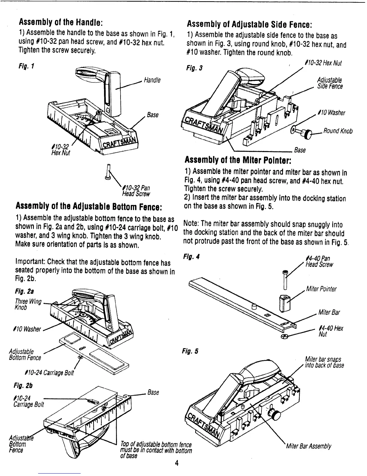
Assemblyofthe Handle:
1) Assemblethe handleto the baseas shown in Fig.1,
using #10-32 panheadscrew, and #10-32 hexnut.
Tightenthe screw securely,
F/O.1
AssemblyofAdjustableSide Fence:
1) Assemblethe adjustable side fence to the baseas
shown in Fig.3, using round knob, #10-32 hex nut, and
#10 washer.Tightenthe round knob.
/10-32HexNut
F
Handle Adjustable
SideFence
Base _ /_....fll I _ _7 #10Washer
RoundKnob
#I0-.32" _,.__...__M _-_-'-C°L:_ \ ...........................................................Base
HexNut _ AssemblyoftheMiterPointer:
AssemblyoftheAdjustableBottomFence:
1)Assembletheadjustablebottomfencetothe baseas
showninFig.2aand2b,using#10-24carriagebolt,#10
washer,and3 wingknob.Tightenthe3 wingknob.
Makesureorientationofpartsisasshown.
Important: Checkthat the adjustable bottom fence has
seatedproperly into the bottom of the baseas shownin
Fig.2b.
1)Assemblethe miterpointerandmiterbarasshownin
Fig.4, using#4-40panheadscrew,and#4-40hexnut.
Tightenthescrewsecurely.
2) Insertthemiterbarassemblyintothedockingstation
onthebaseasshowninFig.5.
Note:The miter bar assemblyshould snap snuggly into
the docking stationand the back of the miter bar should
not protrude past the front of the baseasshown in Fig.5,
Fig. 4 /4-40 Pan
Ftg.2a
ThreeWing
Knob
#lO Washer
Adjustable
BottomFence
/10-24 CarriageBolt
Fig. 2b
/10-24
CarriageBolt
Base
Fig. 5
Miterbarsnaps
intobackofbase
Fence
Topof adjustablebottomfence
mustbein contactwithbottom
ofbase
4
MiterBarAssembly
 Loading...