Unigen Plus & Industrial Unigen - User technical documentation
-D page 9/19
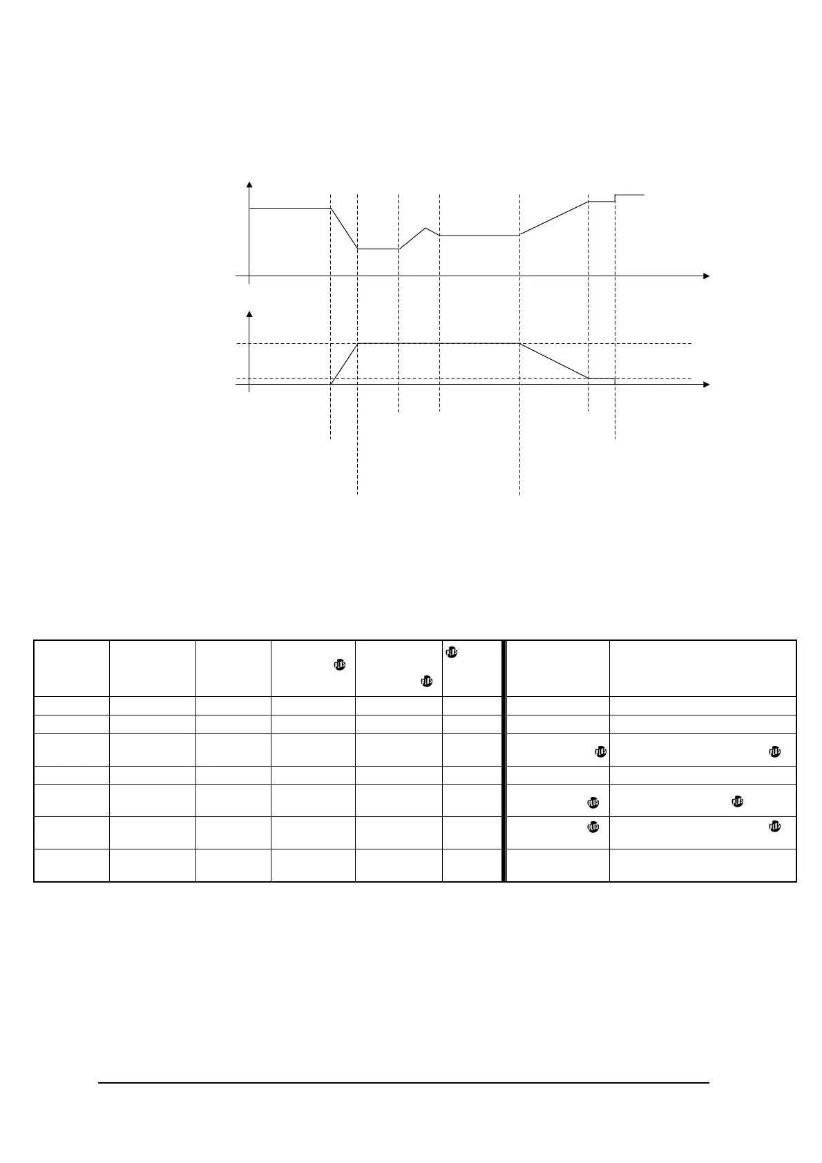
‘Command mode’ and ‘Mains paralleled’ active power behaviour is described in the schematic below.
Mains load
Generator load
Load
impact
Low limit
Unload
request
Paralleling of
the generator
Load setpoint::
Command mode load=kW sepoint input,
Mains paralleld load=paralleling lines input.
Low
limit
stop generator
Active power set point behaviour in different mode is described in the following table.
Terminal 6
'unload'
Terminal 5
'breaker in'
Terminal 4
'droop'
Terminal 38
'mains
paralleled'
Terminal 39
'command
mode'
sw3
'plines/
canbus'
Mode kW management
X open X X X X waiting not
open close close X X X droop frequency
open close open open open OFF
load sharing
paralleling lines(B44-45)
open close open open open ON load sharing canbus(B46-47)
open close open X close X
command
mode
kW setpoint(B41)
open close open close open X
mains
paralleled
paralleling lines(B44-45)
close close open X X X unload
ramp time
potentiometer(RV3)
Close: connected to the 0VDC.
Open: not connected.