3-Series Control System™ Crestron MC3
TCP/IP
NOTE: Preferred method for loading projects and firmware.
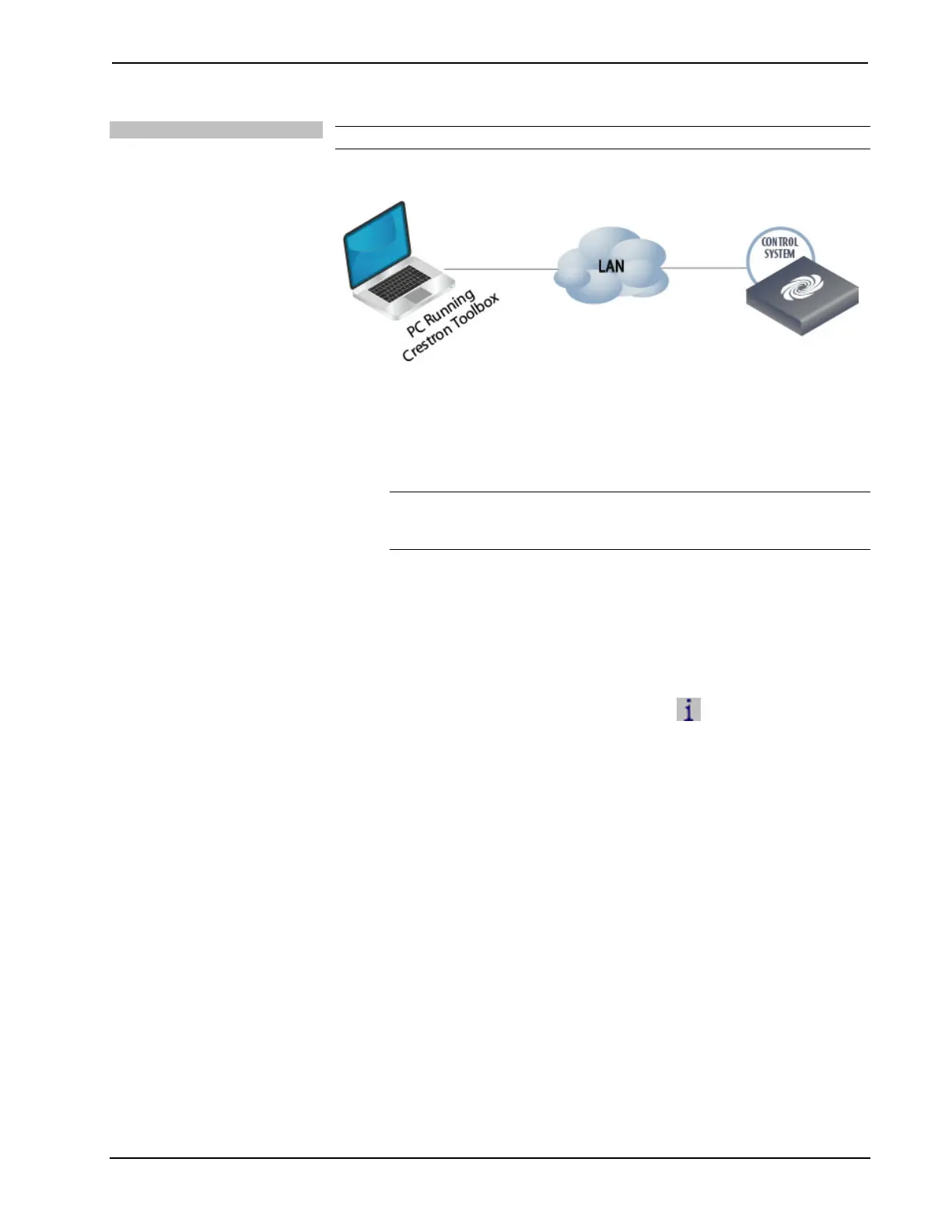
Ethernet Communication
The MC3 connects to PC via Ethernet:
1. Establish USB communication between MC3 and PC.
2. Enter the IP address, IP mask and default router of the MC3 via Crestron
Toolbox (Functions | Ethernet Addressing); otherwise enable DHCP.
NOTE: Use the Device Discovery Tool in Crestron Toolbox to detect all
Ethernet devices on the network and their IP configuration. The minimum
Crestron Toolbox version for the MC3 is 1.23 or later.
3. Confirm Ethernet connection between MC3 and PC. If connecting through a
hub or router, use CAT5 straight through cables with 8-pin RJ-45
connectors. Alternatively, use a CAT5 crossover cable to connect the two
LAN ports directly without using a hub or router.
4. Use the Address Book in Crestron Toolbox to create an entry for the MC3
with the MC3’s TCP/IP communication parameters.
5. Display the “System Info” window (click the
icon) and select the MC3
entry.
6. Use Crestron Toolbox to create the MC3 IP table.
a. Select Functions | IP Table Setup.
b. Add, modify or delete entries in the IP table. The MC3 can have
only one IP table entry.
c. A defined IP table can be saved to a file or sent to the device.
7. When using the MC3 as a “slave”, edit the “master” control system’s IP
table to include an entry for the MC3. The entry should list the MC3’s IP ID
(specified on the MC3’s IP table) and its IP address.
Programs and Firmware
Program or firmware files may be distributed from programmers to installers or from
Crestron to dealers. Firmware upgrades are available from the Crestron Web site as
new features are developed after product releases. One has the option to upload
programs via the programming software or to upload and upgrade via the Crestron
Toolbox. For details on uploading and upgrading, refer to the SIMPL Windows help
file or the Crestron Toolbox help file.
20 • 3-Series Control System™: MC3 Operations Guide – DOC. 7095D
 Loading...