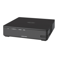
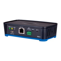
Crestron MC3 3-Series Control System™
Appendix B: Optimum RF Reception Guidelines
Many factors can affect the reliability of RF communication between an RF gateway
and an RF device. While an effort has been made to determine operating
specifications, some specifications are not constant. RF Communication can be
limited by several factors including but not limited to EMI (electromagnetic
interference), intervening objects, antenna orientation and receiver placement. To
obtain maximum reliability and performance, some basic rules for installing RF
transceivers are listed below.
Minimize Interference
RF reception range can be hindered by spurious EMI noise that may interfere with or
mask the desired frequency, thereby reducing useable range. EMI is generated by
any electrical device at various RF noise levels depending on the device. Sources of
EMI include computers, video equipment, digital processors, lighting dimmers,
lighting ballasts, motors or any large AC source. Every effort should be made to
separate any RF transceiver from these sources of RF noise including Audio Visual
equipment in racks. If a gateway must be installed in an equipment rack, make sure
you have ample separation between the equipment and the gateway.
Gateway Placement
Optimum reception for any RF transceiver is obtained by installing the gateway
transceiver in an open area or shelf with a clear line of sight (no obstructions
between gateway and receiver). Crestron recommends that the gateway is at least
five to six feet high for best results. Avoid placing transceivers or transmitters at a
low height or on the ground. Placing RF equipment near metal objects, walls, corners
or metal enclosures will compromise RF propagation and reception. Try to avoid
installing gateways in equipment racks, service rooms, electrical closets or in rooms
other than that which the panel is located.
Antenna Orientation
The antenna orientation on Crestron gateways has considerable effect on range and
reliability. The best orientation is unique to each installation. There are three possible
antenna orientations:
• Point the antenna horizontally (parallel to the ground).
• Point the antenna vertically.
• Point the antenna at a right angle to the gateway.
Never point the antenna downward as this will decrease range and reliability. Refer
to illustrations on the following pages for examples of the different antenna
orientations.
NOTE: RF propagation is best from the sides of the antenna.
Operations Guide – DOC. 7095D 3-Series Control System™: MC3 • 39
 Loading...


