DigitalMedia Switchers Product Manual – DOC. 8418A
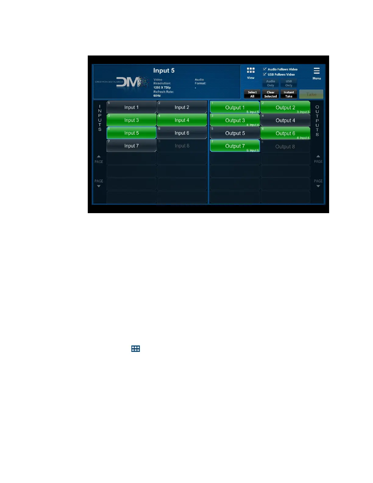
Main Page – Default View (DM-MD8X8-CPU3 Page Shown)
By default, the Main page can display up to 16 inputs and outputs at a time as
applicable to a switcher. Input and output numbers, which correspond to the
inputs and outputs on the rear of the switcher, are displayed. Input and output
names are also displayed. In addition, inputs and outputs that are installed in the
chassis but are not connected to source and display devices, respectively, are
shaded white. Inputs and outputs that are connected to source and display
devices, respectively, are shaded green. Inputs and outputs that are not installed
in the chassis are solid blue. (Information about the blue border around an input
or output is provided later in this procedure.)
In the sample screen above, Inputs 1, 2, 6, and 7 and outputs 4 and 5 are shaded
white indicating that they are installed in the chassis. Inputs 3, 4, and 5 and
outputs 1, 2, 3, 6, and 7 are shaded green indicating that they are connected to
source and display devices, respectively. Input 8 and Output 8 are solid blue
indicating that they are not installed in the chassis.
2. If desired, change the view from the default view to the alternate view by clicking
the View icon ( ) in the upper-right section of the page.

 Loading...