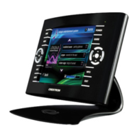
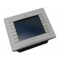
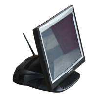
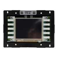
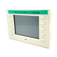
Crestron TPS-6X Series Isys™ 5.7” Wireless Touchpanels
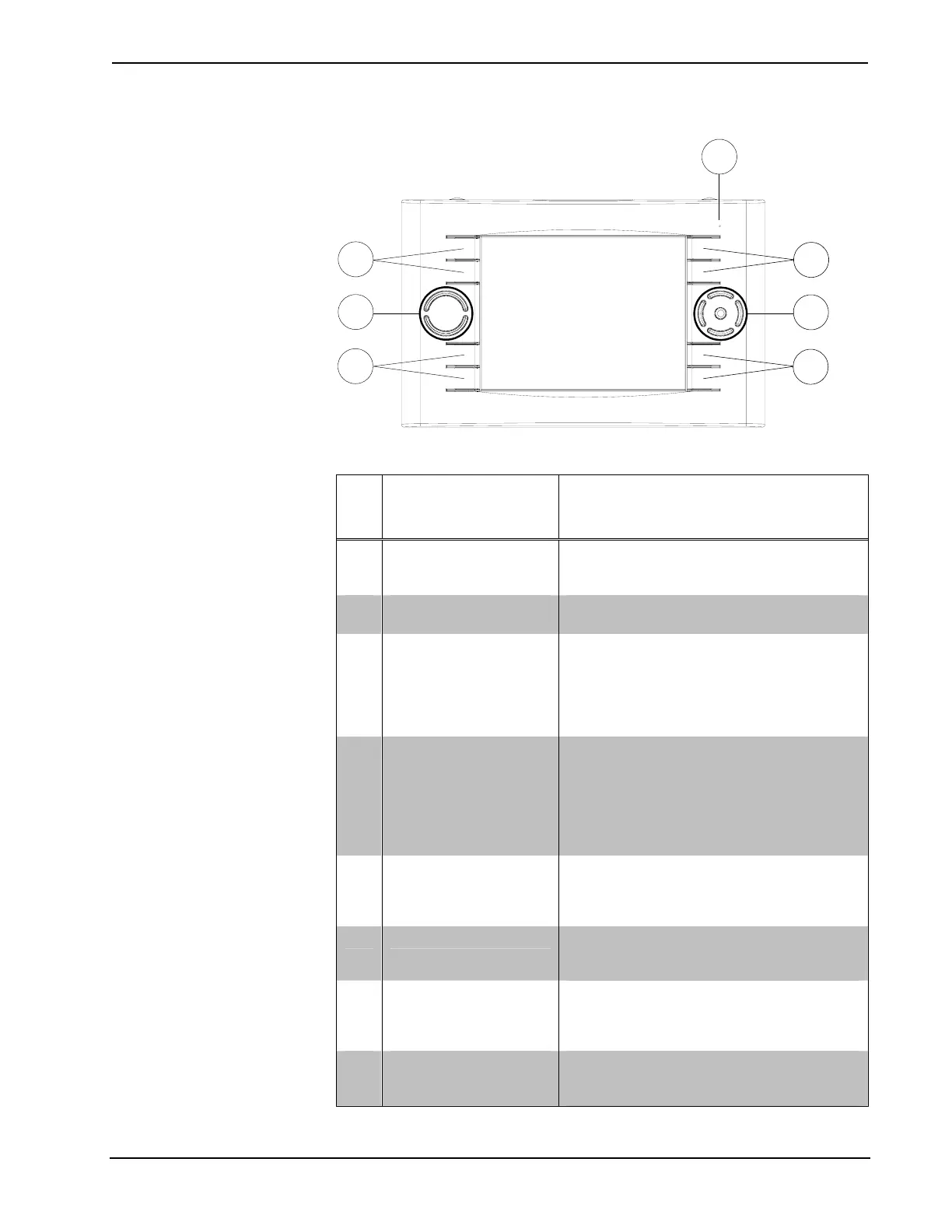
TPS-6X (Front View)
7
8
5
6
6
6
6
Connectors, Controls & Indicators
# CONNECTORS,
CONTROLS &
INDICATORS
DESCRIPTION
1
DOCKING STATION
CONNECTOR
(1) Multi-pin connector; mates with the
docking port on the TPS-6X-DS
(or TPS-6XNL-DS) Docking Station.
2 BATTERY SWITCH
(1) Rear panel recessed DIP switch, shuts off
battery for long term storage.
3 SLEEP
(1) Programmable top-mounted pushbutton
(left “trigger” key), initiates Sleep mode when
docked; turns power on/off when undocked;
also resets touchpanel if held for five
seconds, starting up at first page of the
installed project.
4 BRIGHTNESS
(1) Programmable top-mounted pushbutton
(right “trigger” key), normally sets display
brightness level. Toggles between high,
medium, low and standby. Toggling can be
enabled/disabled from setup menu (refer to
“BACKLIGHT” which starts on page 33 for
details).
5 BATTERY LED
(1) Green LED, indicates battery condition
and charging status when docked.
Flashing indicates battery is charging;
Steady on indicates battery is fully charged.
6 HARD KEYS
(8) Optional programmable pushbuttons;
engravable backlit* text (sold separately);
default engraving included.
7 UP/DOWN
(2) Optional programmable “up/down”
pushbuttons, backlit, engravable backlit* text
on bezel (sold separately); default engraving
included.
8 THUMBPAD
(5) Optional programmable pushbuttons for
4-way directional navigation and “enter”,
backlit.
* Text engraving is not backlit on white models.
Operations Guide – DOC. 6875B Isys™ 5.7” Wireless Touchpanels: TPS-6X Series • 11
 Loading...