EasyManua.ls Logo

Crown Boiler PHNTM080 - Page 83

Crown Boiler PHNTM080
146 pages
Print Icon
To Next Page IconTo Next Page
To Previous Page IconTo Previous Page
Loading...
81
P3‐9
BoilerControl(R7910B)
+V
J3‐A
J3‐A
‐V
J3‐B
J3‐B
MB1
MB2
RJ45
(MB2‐2)
Panasonic
GT02
Display
SD+
RD+
SD‐
‐5V
+5V
RD‐
RJ45
(MB2‐1)
A
‐V
P10‐7
P10‐8
P10‐9
ReturnSe nsor
SupplySensor
Spark
J1‐2
J9‐4
J9‐5
J9‐6
WiringLegend
BoilerControl(R7910B)
AT140B
L
N
DHWPump
P3‐4
P3‐1
P3‐6
DHW(L)
SYS(L)
BoilerPump
DHW(N)
SYS(N)
SystemPump
G
J8‐3
J8‐2
J6‐3
J4‐10
J7‐7
J4‐12
J8‐1
J5‐1
J6‐2
J5‐2
GasValve
Sump
Press.Sw.
ExternalLimit
(IfUsed)
Ext.
Limit
P8‐12
P8‐3
P8‐4
P8‐5
CHT’stat
DHW
Thermostat
Ext.
Limit
DHW
T’Stat
DHW
T’Stat
R W
FlowSw.
J3‐D
J3‐R
J3‐C
Igniter
Flame
Rod
P8‐9
P8‐8
FactoryWireHarness
PCBTrace/Components
Fieldwiring
Connector
Screw
Terminal
P3‐3
L3‐1
J4‐4
J4‐2
J4‐6
J4‐3
J4‐5
J4‐7
CombustionFan
(120VConn.)
1 3
2
F1(6.3A
SlowBlow)
P3‐10
P3‐11
P3‐7
P3‐12
J8‐10
J8‐4
J8‐9
J8‐8
J8‐11
J8‐5
J10‐7
J10‐8
P10‐1
P10‐3
Header
Sensor
Outdoor
Sensor
J6‐7
J6‐8
P8‐11
P8‐10
ECOM
D
R
C
RJ45
(ECOM)
FlueGasSensor
1(DC+)
2(Tach.)
4(PWM)
5(DC‐)
J2‐3(FanPWM)
J2‐4(DC‐)
J2‐1(Tach.)
J2‐2(DC+)
CombustionFan
(DCConn.)
F2(1.6A
SlowBlow)
Modbus
P10‐2
Internal,non
replaceable2amp
GroundScrew
BottomPanel
B
P12‐3
P12‐4
P8‐2
P12‐1
LWCOSensing
Circuit(IfUsed)
2
1
J6‐1
P3‐2
L1‐1 L1‐2
L3‐2
L2‐1 L2‐3
P8‐6
P8‐7
C
Thermal
Fuse
GroundedtoBoiler
FrameviaPCB
Standoff/Mounting
Screw
AirProving
Switch
LWCO
JUMPER
(Std)
OR
P12‐2
OR
JUMPER
(Std)
Alarm
Condensate
Trap
120VLine
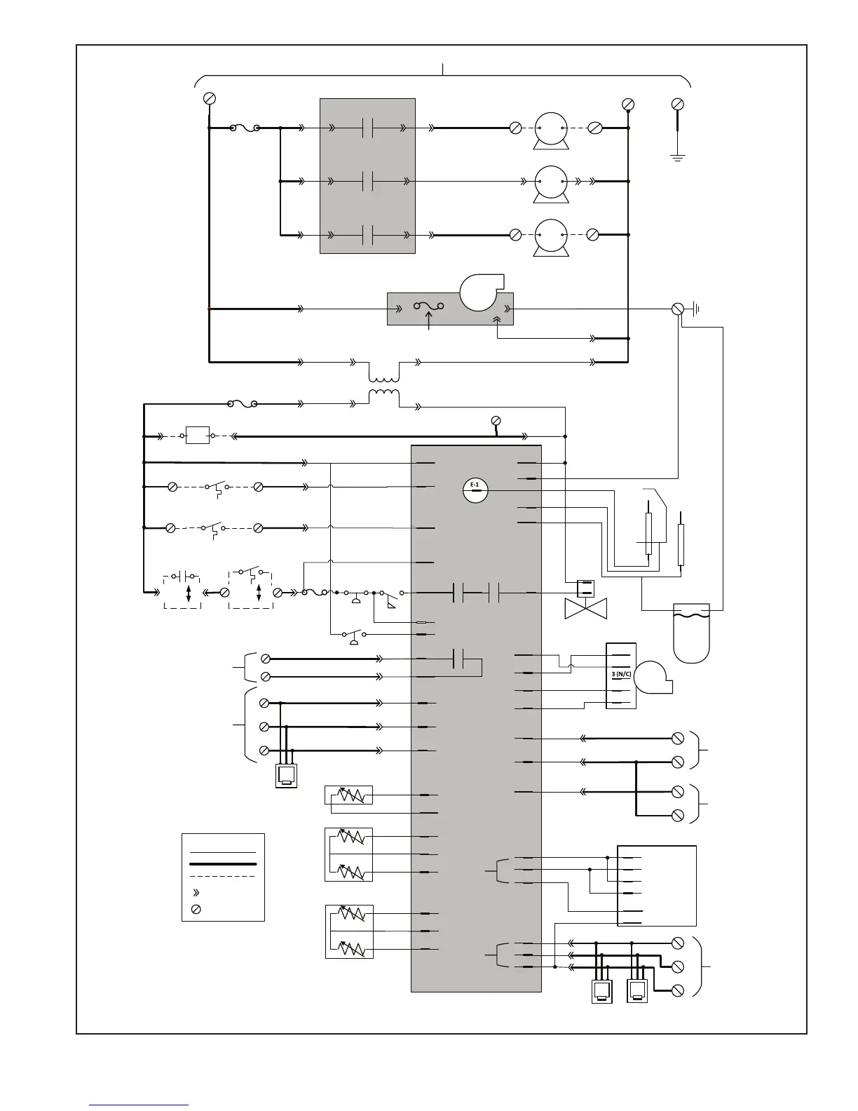
FIGURE 10.5: INTERNAL LADDER DIAGRAM