Page 33
Com-Tech Power Amplifiers
Reference Manual
Protection
Com-Tech amplifiers are protected against shorted,
open or mismatched loads; overloaded power sup-
plies; excessive temperature, chain destruction phe-
nomena, input overload damage and high-frequency
blowups. They also protect loudspeakers from input/
output DC and turn-on/turn-off transients.
If unreasonable operating conditions occur, the pat-
ented ODEP circuitry proportionally limits the drive
level to protect the output devices, particularly in the
case of elevated temperature. Transformer overheat-
ing results in a temporary shutdown of both channels.
The transformer automatically resets itself when it has
cooled to a safe temperature. Controlled slew rate volt-
age amplifiers protect against RF burnouts, and input
overload protection is provided by current-limiting re-
sistance at the input.
Turn On: The four-second turn on delay prevents dan-
gerous turn-on transients. “Soft-start” circuitry provides
low inrush so power sequencers are rarely needed
with multiple units.
Note: The turn-on delay time may
be changed. Contact Crown’s Technical Support
Group for details.
Circuit Breaker: Circuit breaker current ratings vary
based on the Com-Tech model and AC mains voltage.
All 100/120 VAC Units:
Com-Tech 210 : 8 amperes.
Com-Tech 410 : 12 amperes.
Com-Tech 810 : 20 amperes.
Com-Tech 1610 : 30 amperes.
All 220/240 VAC Units:
Com-Tech 210 : 4 amperes.
Com-Tech 410 : 6 amperes.
Com-Tech 810 : 10 amperes.
Com-Tech 1610 : 20 amperes.
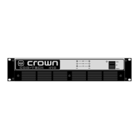
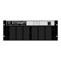
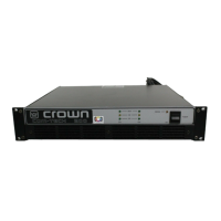
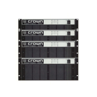
Construction
Durable black powdercoat finish on the steel chassis,
front panel Lexan overlay, and specially-designed
flow-through ventilation from front to side panels.
Cooling: Internal heat exchangers with on-demand
forced air cooling (fan is optional for the North Ameri-
can Com-Tech 210 ; see Sections 3.2.1 and 8.2).
Dimensions: 19 inch (48.3 cm) standard rack mount
width (EIA RS-310-B), 16 inch (40.6 cm) depth behind
mounting surface, and 0.25 inches (0.6 cm) in front of
mounting surface. Amplifier height varies among the
available models and with different AC power require-
Indicators
Enable: This amber indicator shows the on/off status of
the unit’s low-voltage power supply and the activation
of the energy-saving mode.
SPI (Signal Presence Indicator):
Each channel has a
green indicator that flashes to show audio output.
IOC (Input/Output Comparator): Each channel has a
yellow indicator that flashes if the output waveform differs
from the input waveform by 0.05% or more. The LEDs act
as sensitive distortion indicators to provide
proof of distor-
tion-free performance
.
ODEP (Output Device Emulation Protection): Each
channel has a green multifunction indicator that shows
the channel’s reserve energy status. Normally, the
LEDs are brightly lit to show that reserve energy is
available. In the rare event that a channel has no re-
serve, its indicator will dim in proportion to ODEP limit-
ing. An ODEP indicator may also turn off under other
more unusual circumstances (see Section 4.2).
Input/Output
Input Connector:
A barrier block on the standard
PIP2-BB with three-terminal balanced connections for
input to each channel and test points for a DVM.
Input Impedance: Nominally 20 K ohms, balanced.
Nominally 10 K ohms, unbalanced.
Input Sensitivity: Settings include 0.775 volts for 8/4-
ohm output, 0.775 volts for 70-volt output, and a volt-
age gain of 26 dB.
Output Connector: A back panel barrier block with
two-terminal connections for each output channel.
Output Impedance: Less than 10 milliohms in series
with less than 2 microhenries (see Figure 6.11).
DC Output Offset: Less than ±10 millivolts.
RSVP: An RJ11 modular connector on the back panel
interfaces with an RSVP to provide remote control of a
large number of amplifier power on/off functions.
Output Signal
Dual: Unbalanced, two-channel.
Bridge-Mono: Balanced, single-channel. Channel 1
controls are active; Channel 2 should be turned down.
Parallel-Mono: Unbalanced, single-channel. Chan-
nel 1 controls are active; Channel 2 is bypassed.