www.SteamPoweredRadio.Com
I
I
I
I
I
I
I
I
I
I
I
I
I
I
I
I
I
I
I
2
.1
UNPACKING
As
soon
as
the amplifier shipment is received,
please inspect for any damage incurred in transit.
Since the unit was carefully inspected and tested
at
the factory,
it
left the factory unmarred.
If
dam-
age
is found, notify the transportation company
immediately. Only the consignee may institute a
claim with the carrier for damage during ship-
ment. However,
CROWN
will cooperate fully in
such
an
event.
Be
sure to
save
the carton
as
evi-
dence
of
damage for the shipper's inspection.
Even
if
the
unit
arrived in perfect condition -
as
most do -
it
is advantageous to save the packing
materials. They will prove valuable in preventing
damage should there ever be occasion to transport
or ship the uni
t.
Note the carton and internal pack -
each
is
designed for protection during transit.
Do
not ship the unit without this factory pack!
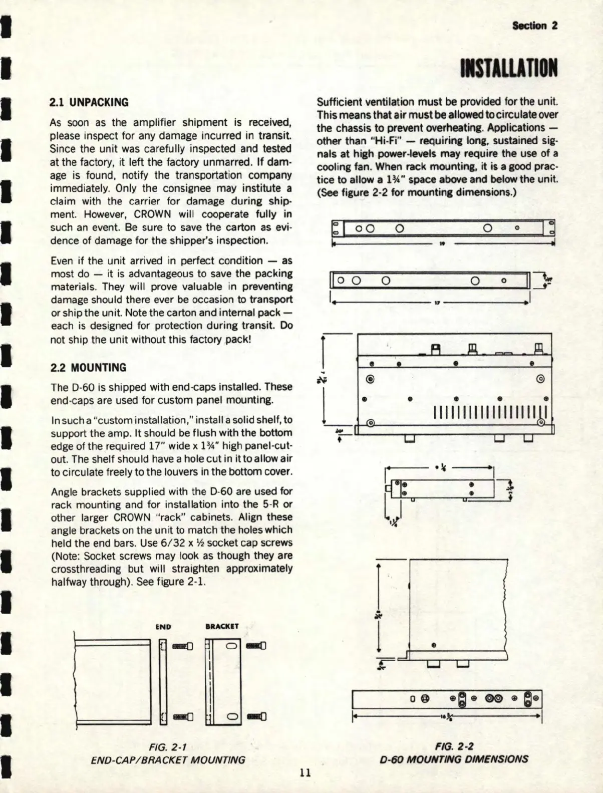
2.2
MOUNTING
The D-60 is shipped with end-caps installed. These
end-caps are used
for
custom panel mounting.
In such a
"c
ustom installati
on
," install a solid shelf, to
support the amp. It should be flush with the bottom
edge
of
the required 17" wide x 1 ¾" high panel-cut-
out. The shelf should have a hole cut in it to allow
air
to circulate freely to the louvers in the bottom cover.
Angle brackets supplied with the D-
60
are used for
rack mounting and for installation into the
5-R
or
other larger
CROWN
"rack" cabinets. Align these
angle brackets
on
the
unit
to match the holes which
held the end bars.
Use
6/ 32 x ½ socket cap screws
(Note: Socket screws may look as though they are
crossthreading
but
will straighten approximately
halfway through).
See
figure 2-1.
IND
IIACKIT
]
0
I
I
I
I
I
'
1111()
.:i
I
l
0
FIG.
2-1
END-CAP/ BRACKET MOUNTING
11
Section
2
ISTILLITION
Sufficient ventilation
must
be provided for the unit.
This means that
air
must
be
allowed
to circulate over
the chassis
to
prevent overheatint. Applications -
other than "Hi-Fi" - requirin1 Iona, sustained sig-
nals
at
hi&h power-levels may require the use
of
a
coolin1 fan. When rack mountin1,
it
is a
1ooct
prac-
tice to allow a
1
3
/4"
space above and below the unit.
(See
fi1ure 2-2 for mountin1 dimensions.)
~I
oo
o
0
0
Id
..
ilo
o o 0
0
Ii]!
'-------
..
I
1-
L-,.__---.1..l---,C~
..
'ff
@
l_..LJ·~-·
_1_11_,1_11
_111_1
i_11
_111--->..:1
o:.<-+,i
~-~
·~
h
•
•
l.,..1
,
0
l
•
i
•
o@
l+------k'-----1
FIG.
2-2
0 -
60
MOUNTING DIMENSIONS