www.SteamPoweredRadio.Com
14
40 .
04
RL
RL
.A>6
Rs
LOAD
Rs
SOUICI
ANNEALED
30
.1
RESISTANCE
DAMPING
RESISTANCE
COPPER
(e
hfflsl
F
ACTOR
(eh..,,)
2-COND,
WIii
100
(AWO)
20
,,
..
,,
.4
s
-•2•
10
so
.
24
...
~
••
-•22
15
«
20
'l
'
20
10
s
2
10
2000
9
,
(;
2
4
5000
I
.s
-
•4
•
•2
7
-•
o
10
-•oo
6
.1
-=•oooo
.OS
s
20
4
40
.01
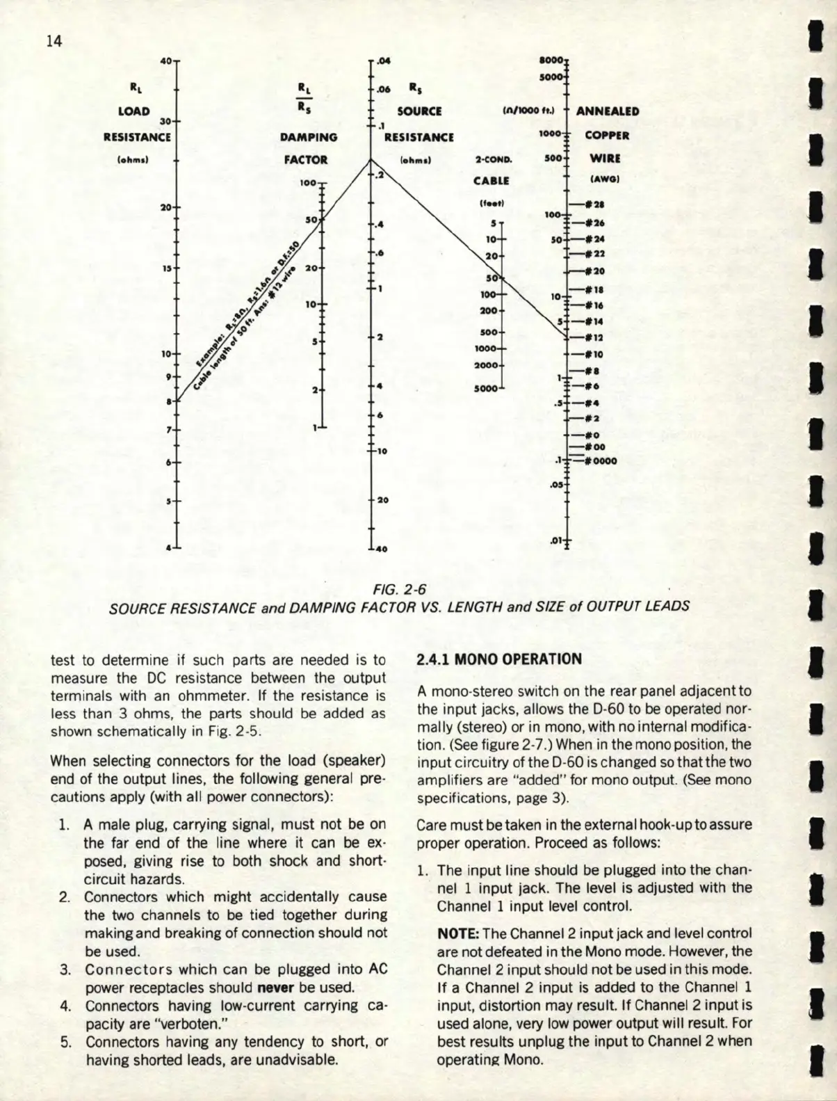
FIG.
2-6
SOURCE RESISTANCE
and
DAMPING
FACTOR
VS.
LENGTH
and
SIZE
of
OUTPUT LEADS
test
to
determine if such parts are needed is to
measure the
DC
resistance between the output
terminals with an ohmmeter. If the resistance
is
less than 3 ohms, the parts should be added as
shown schematically in Fig. 2-5.
When
selecting connectors
for
the load (speaker)
end
of
the output lines, the following general pre-
cautions apply (with all power connectors):
1. A male plug, carrying signal,
must
not
be on
the far end
of
the line where
it
can be ex-
posed, giving rise
to
both shock and short-
circuit hazards.
2. Connectors which
might
accidentally cause
the two channels
to
be tied together
during
making and breaking
of
connection should not
be
used.
3.
Connectors
which can be plugged into
AC
power receptacles should
ne
ver be used.
4. Connectors having low-current carrying ca-
pacity are "verboten."
5. Connectors having any tendency to short,
or
having shorted leads, are unadvisable.
2.4.1
MONO
OPERATION
A mono-stereo switch on the rear panel adjacent
to
the
input
jacks, allows the D-
60
to
be operated nor-
mally (stereo)
or
in mono, with no internal modifica-
tion. (
See
figure 2-7 .) When in the mono position, the
input circuitry
of
the D-
60
is changed so that the two
amplifiers are "added" for mono output.
(See
mono
specifications, page 3).
Care must be taken in the external hook-
up
to assure
proper operation. Proceed
as
follows:
1. The input line should be plugged into the chan-
nel 1 input jack. The level is adjusted with the
Channel 1
input
level control.
NOTE
: The Channel 2 input jack and level control
are not defeated in the Mono mode. However, the
Channel 2 input should not be used in this mode.
If
a Channel 2
input
is
added
to
the Channel 1
input, distortion may result.
If
Channel 2 input is
used alone, very low power output will result. For
best results unplug the input
to
Channel 2 when
operatinR Mono.
I
I
I
I
I
I
I
I
I
I
I
I
I
I
I
I
I
I
I