www.SteamPoweredRadio.Com
I
I
I
I
I
I
I
I
I
I
I
I
I
I
I
I
I
I
I
2.3
NORMAL
HI-Fl
INSTALLATION
1.
Two-conductor speaker cables must connect to
the
OUTPUT
dual binding posts using terminal
lugs, tinned ends,
or
"banana" plugs.
2.
Since the 0-
60
is a "basic amplifier," the main
outputs of the control-center or "preamplifier"
must
be
connected via shielded audio-cables to the
two jacks marked I
NPUT.
Use
RCA-pin at preamp
and standard
¼ in. phone-plug at the D-60.
The
two cables should be tied parallel along their
entire length using the accessory cable ties.
3. U/ L requirements prefer a 3-wire
AC
power
conne
c
tor
; however,
proper
connections to a
switched outlet on the control center requires the
use
of a 3-to-2 wire adapter.
NOW
, plug the
AC
into a
S'!'it
c
hed
outlet
on
the control center.
4.
Your Control Center may now
be
turned on.
Then
advance the 0-60 Input-Gain Controls about
½
-open
(150° clockwise).
When
using the
CROWN
IC
-150A Control-Center,
the
VOLUME
should attain almost full rotation
(2
to 4 o'clock) for loudest "concert-hall" volume.
If at 3 o'clock the volume
is
low, increase the D-60
input gain controls;
if
too
high,
de
c
rease
the D-60
gains.
To assure maximum enjoyment and full speaker
protection, read the following detailed sections on
OUTPUTS,
I
NPUTS
and Chapter 3-0PERATION.
2.4
CONNECTING
OUTPUT
LINES
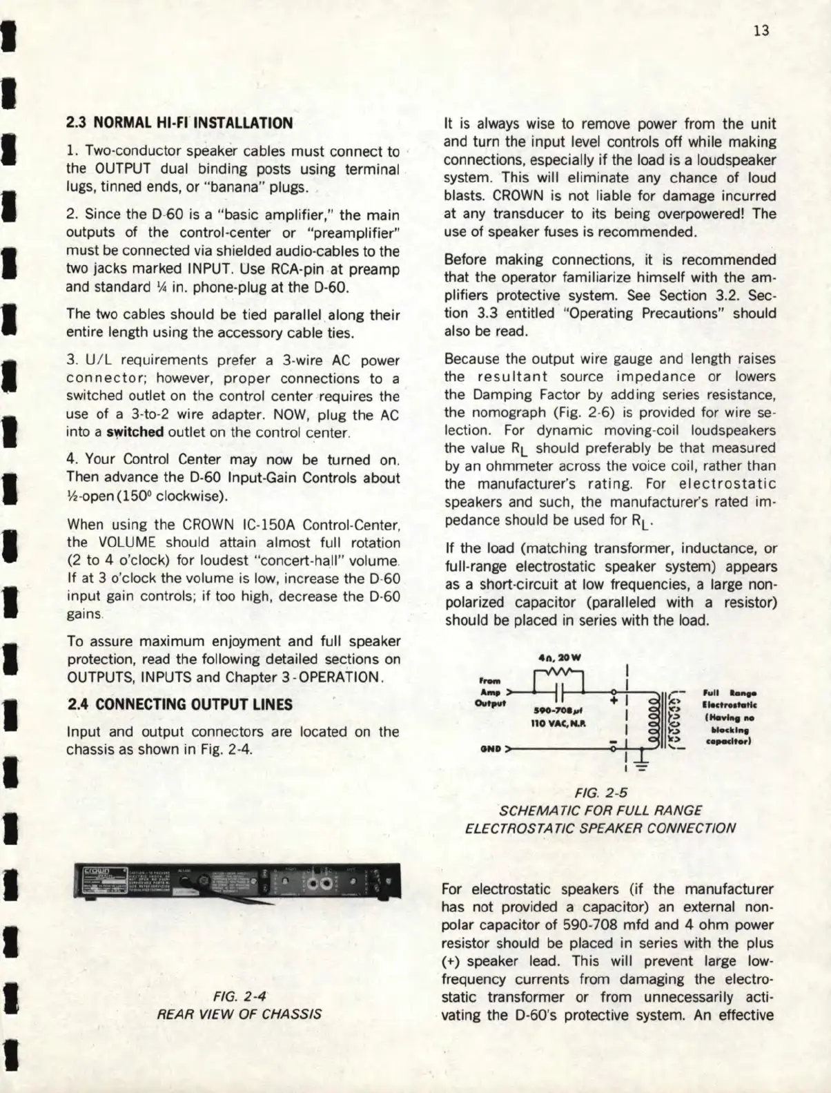
Input and output connectors
are
located
on
the
chassis
as
shown in
Fig
. 2-4.
FIG.
2-4
REAR VIEW
OF
CHASSIS
13
It
is
always wise to remove power from the unit
and
turn the input level controls off while making
connections, especially
if
the load is a loudspeaker
system. This will eliminate any chance of loud
blasts.
CROWN
is not liable for damage incurred
at any transducer to its being overpowered! The
use of speaker fuses is recommended.
Before making connections,
it
is recommended
that the operator familiarize himself with the am-
plifiers protective system.
See
Section 3.2.
Sec
-
tion 3.3 entitled "Operating Precautions" should
also
be
read.
Because the output wire gauge and length raises
the
resultant
source impedance or lowers
the Damping Factor
by
adding series resistance,
the nomograph
(Fig.
2-6)
is
provided for wi
re
se
-
lection.
For
dynamic moving-coil loudspeakers
the value
RL
should preferably
be
that measured
by
an
ohmmeter across the voice coil, rather than
the manufacturer's
rating
.
For
electrostat
ic
speakers
and
such, the manufacturer's rated im-
pedance should be used for
RL
.
If the load (matching transformer, inductance,
or
full-range electrostatic speaker system) appears
as
a short-circuit at low frequencies, a large non-
polarized capacitor (paralleled with a resistor)
should be placed in series with the load.
4n
,
20
W
I
,,_
I
A-.
+ I
,~-
fu
ll
.__.
Output
....
,
.....
tic
S
90
·
7M
....
I
r~
,.......,._
110
VAC,NJl
l
~
.......
,
...
Ir>
·--,
GND
'--
FIG. 2-5
SCHEMA
TIC
FOR FULL RANGE
ELECTROSTATIC SPEAKER CONNECTION
For electrostatic speakers
(if
the manufacturer
has
not provided a capacitor)
an
external non-
polar capacitor of 590-708 mfd and 4 ohm power
resistor should
be
placed in series with the plus
(+) speaker lead. This will prevent large
low-
frequency currents from damaging the electro-
static transformer or from unnecessarily acti-
vating the D-60's protective system.
An
effective