www.SteamPoweredRadio.Com
I
I
I
I
I
I
I
I
I
I
I
I
I
I
I
I
I
I
I
APPLICATION
NOTE
1
Evaluating the V-1 (volt-ampere) needs
of
a load:
Many loads exhi
bit
large reactances (or energy
storage), which limits a power amplifier's ability
to deliver a maximum power.
If
a load stores en-
ergy, which in turn flows back into the amplifier,
it
is clear that the maximum power efficiency
of
the system is not being achieved. Power that flows
back into a linear amplifier must necessarily be
dissipated in the form of heat. A pure reactance
is not capable of dissipating any power; therefore
to drive such a load would only cause power am-
plifier heating.
In practice all loads exhibit some energy dissipa-
tion - however large their energy storage char-
acteristics may
be
. The ideal coupling to any load
is one that optimizes the desired dissipation com-
ponent while minimizing the reactive or stored-
energy component that is
seen
by the amplifier's
output terminal
s.
In applications where the input
is
sinusoidal and
of small proportional frequency deviation, a rela-
tively stable load may be resonantly tuned to pre-
sent a
real
value of
imp
edance to the amplifier.
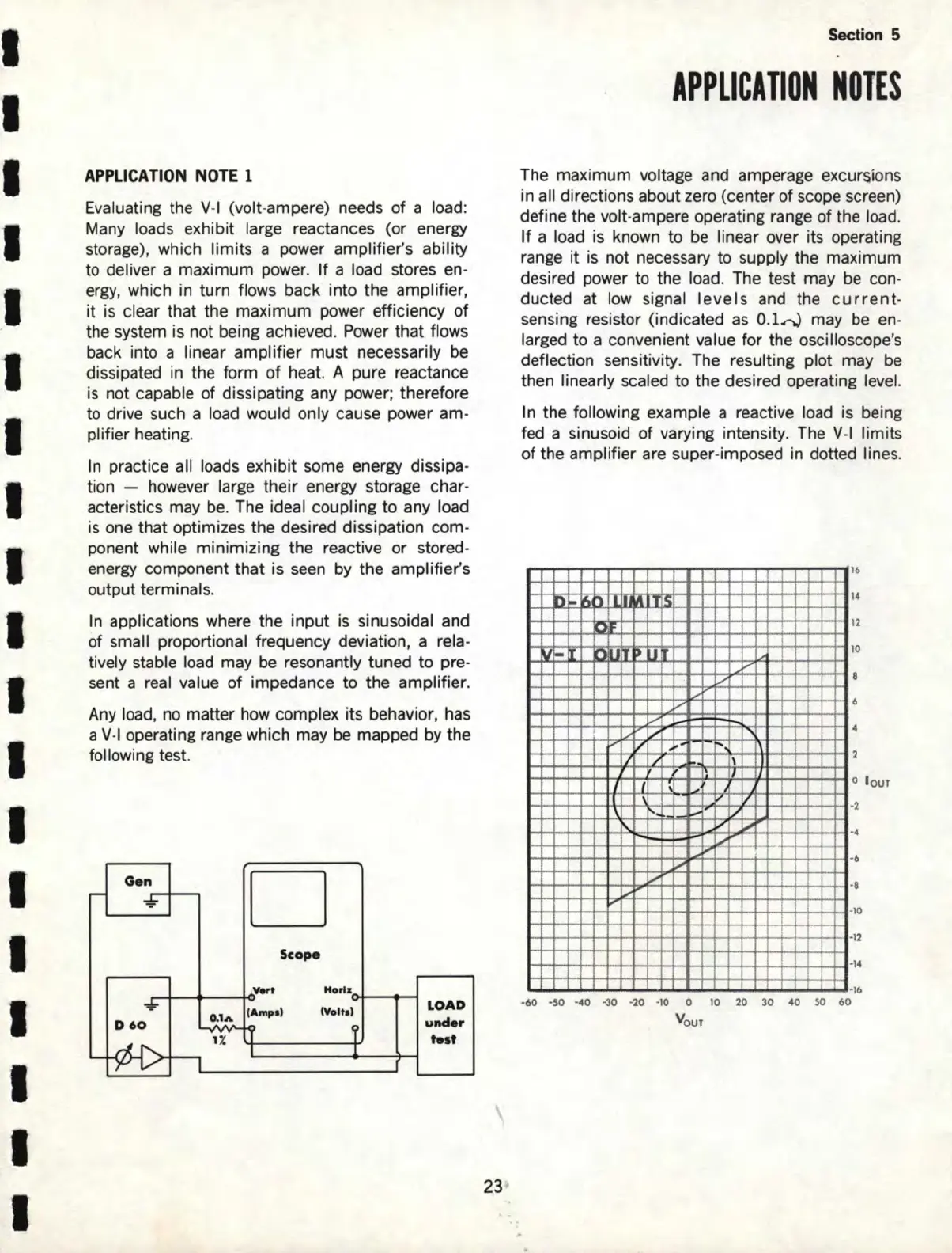
Any load, no matter how complex its behavior, has
a V-1 operating range which may
be
mapped by the
following test.
Gen
□
D60
V.rt
-----t-O
Scope
0.1A
(Ampe)
1%
LOAD
under
t.st
23
Section 5
APPLICATION
NOTES
The maximum
vo
lt
age
and amperage excursions
in all directions about zero (center of scope screen)
define the volt-ampere operating range of the load.
If
a load is known to
be
linear over its operating
range
it
is not necessary to supply the maximum
desired power to the load. The test may be con-
ducted
at
low signal
levels
and the
current
-
sensing resistor (indicated
as
0.lrJ
may
be
en
-
larged to a convenient value for the oscilloscope's
deflection sensitivity. The resulting plot may
be
then linearly scaled to the desired operating level.
In the following example a reactive load is being
fed a sinusoid of varying intensity. The V-1 limits
of the amplifier are super-imposed in dotted lin
es.
ru
..
..
. I I
,.
I
ti
M
,-
I
II' u
/
~
V
......
I/
...
V
lo'
"·
J
,
I~
j
I '
'
I
I
II'
'
'·
_..
,-
.,
~
....
I;'
I;'
L,
...
-
·60
·SO ·40
·30
·
20
·1
0 O 10
Yo
ur
..
V
\
\
I
'
I/
,
,I
~
--,-
.-
--
,_
I
I
1
4
2
0
8
6
4
2
1
1
1
o l ouT
2
6
B
10
·1
2
·14
·16
20
30
40
so
60