www.SteamPoweredRadio.Com
I
I
I
I
I
I
I
I
I
I
I
I
I
I
I
I
I
I
I
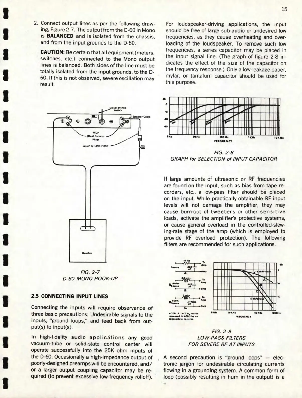
2. Connect output lines as per the following draw-
ing, Figure 2-
7.
The output from the D-60 in Mono
is
BALANCED
and is isolated from the c
ha
ssi
s,
and
fr
om the input grounds to the D-60.
CAUTION:
Be
certain that all equipment (meters,
switches,
et
c.) connected to the Mono output
lines
is
balanced. Both sides of the line must
be
totally isolated from the input grounds, to the D-
60.
If
this is not observed, severe
os
cillati
on
may
result.
FIG.
2-7
D-
60
MONO
HOOK
-UP
2.5
CONNECTING
INPUT
LINES
Connecting the inputs will require observance
of
three basic precautions: Undesirable
signals
to the
inputs, "ground loops," and feed back from out-
put(s) to input(s).
In high-fidelity
audio
applications
any good
vacuum-tube or solid-state control center will
operate successfully into the 25K ohm inputs
of
the D-60. Occasionally a high-impedance output
of
poorly-designed preamps will
be
encountered, and/
or a larger output coupling capacitor may
be
re-
quired (to prevent excessive low-frequency rolloff).
15
Fo
r loudspeaker-driving applications, the input
should
be
free of large sub-audio or undesired low
frequencies,
as
they cause overheating and over-
loading
of
the loudspeaker.
To
remove
su
ch
low
fr
equencies, a series
ca
pacitor may be placed in
the input signal lin
e.
(
Th
e gra
ph
of figu
re
2-8 in-
dicat
es
the effe
ct
of the size of the capacitor
on
the
fr
equency response.) Only a low
-l
eaka
ge
paper,
mylar, or t
an
tal
um
ca
pa
citor should
be
use
d for
this p
ur
pose.
..
0
·•
·U
"""~
--
i,..,"'
1.-'
~
i,,.~~
1
........
....
~
...
~
I,,"
ir·
IN
■
,
.....
IKM
■
IOKN
■
JIIQUINC'I'
FIG. 2-8
GRAPH
for
SELECTION
of
INPUT CAPACITOR
If large amounts of ultrasonic
or
RF
frequencies
are found on the input, such
as
bias from tape
re
-
corders,
et
c.
, a low-pass filter should
be
plac
ed
on
the input. While practically-obtainable
RF
input
levels will not damage the amplifier, they may
cause burn-out
of
tweeters
or other
sensitive
loads, activate the amplifier's protective systems,
or cause general overload in the controlled-slew-
ing-rate stage of the amp (which is employed to
provide
RF
overload protection).
The
following
filters are recommended for such applications.
~
,.
.~vv_.~-
-.
.
"'I
J C. •
....
"'~
~
.,
....
~
\.
~
"'~
'
~
~
1, \
12Alo
....
.
"'
\
...
•
..
20
NOT11 A
i,...z
•••9tl
..
...
,.....
..
toOl\.,,eA
......,..
..
,..
,
.....
.
411M,
to•M
•
40.N,
lOOKHa
PUQUINCT
FIG. 2 -9
LOW
-PASS
Fil
TERS
FOR SEVERE RF
AT
INPUTS
A second precaution
is
"ground loops" - elec-
tronic jargon for undesirable circulating currents
flowing in a grounding system. A common form of
loop (possibly resulting in hum in the output)
is
a