RADIO TROUBLESHOOTING
How can I fail my signalling paths without having to disconnect them?
To fail each path select menu options N or O
• Menu N – Fails primary path
• Menu O – Fails secondary path
Using the A or B button scroll until you see menu N or O on the display, then press and hold the C
button until you see (_). Press the A or B buttons to toggle between Y & N, then press C to select the
option.
Y = Yes, fail the path.
N = Normal, restore the failed path.
“Y” will only fail the path for a total of 15 minutes.
What does the flashing dot in the right-hand side of the display indicate?
The flashing dot in the right-hand corner of the display indicates that DualCom Pro is actively
transmitting data.
How can I check the signal strength of each radio module?
You can check the signal strength of each radio module on a commisioned device via the My Base App.
Alternatively you can toggle between the signal strength of each radio module, move DIP Switch 4 of
the secondary radio module to ON or OFF (opposite position). The display of the DualCom Pro will read
GSM 1 or GSM 2 followed by the Radio Access Technology (RAT) and signal strength between 1-10 (10-
100%) dependant on the radio module.
Does my unit have a roaming SIM?
Yes, all variants of DualCom Pro devices come with at least 2 Roaming 4G SIMs
If the signal strength of my DualCom Pro is under 3 (30%) what can I do to improve my
signal strength?
For all radio variants:
• Avoid coiling the aerial cable
• Move the aerial away from electrical equipment/wiring
• Move the aerial to a higher point in the property or closer to a window/door
Where you are using a dual radio variant, it is possible to purchase an additional Radio/Wi-Fi Module
Enclosure with in-built aerials. This will enable you to locate the secondary radio module in a dierent
location. Please visit the CSL Installer Shop for more information.
12
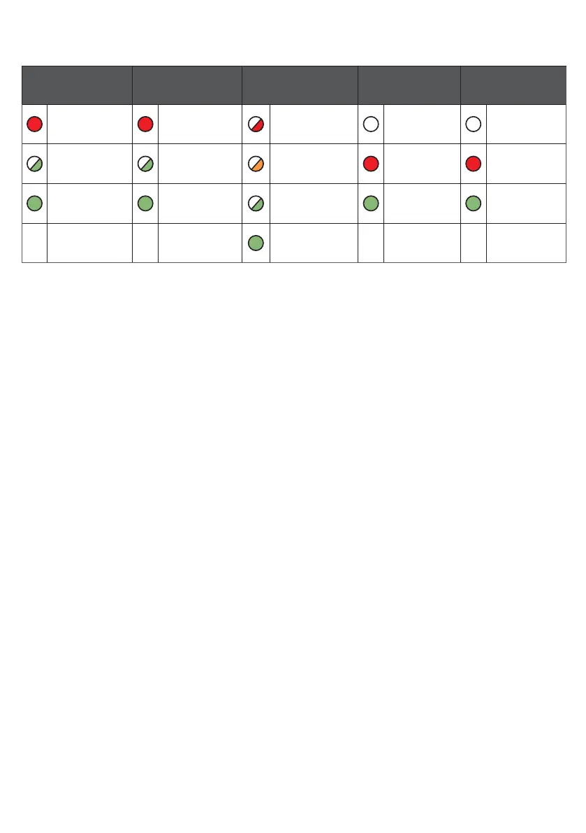
LED 1
PRIMARY INTERFACE
LED 2
SECONDARY INTERFACE
LED 3
ERRORS
LED 4
SERIAL CABLE
LED 5
RS422 BUS
Red Solid Light =
No Signal
Red Solid Light =
No Signal
Red Flashing Light
= Fatal Configuration
Errors
No Light =
No connection
No Light =
No connection
Green Flashing Light =
Poor But Usable Signal
Green Flashing Light =
Poor But Usable Signal
Amber Flashing Light =
Not commissioned
Red Solid Light =
Receiving data from
panel
Red Solid Light =
Receiving data
from panel
Green Solid Light =
Good Signal
Green Solid Light =
Good Signal
Green Flashing Light =
Communicating with
non-fatal errors
Green Solid Light =
Transmitting data
Green Solid Light =
Transmitting data
Green Light Solid =
Commissioned with
no errors
Figure 10 - LEDs DURING NORMAL OPERATION