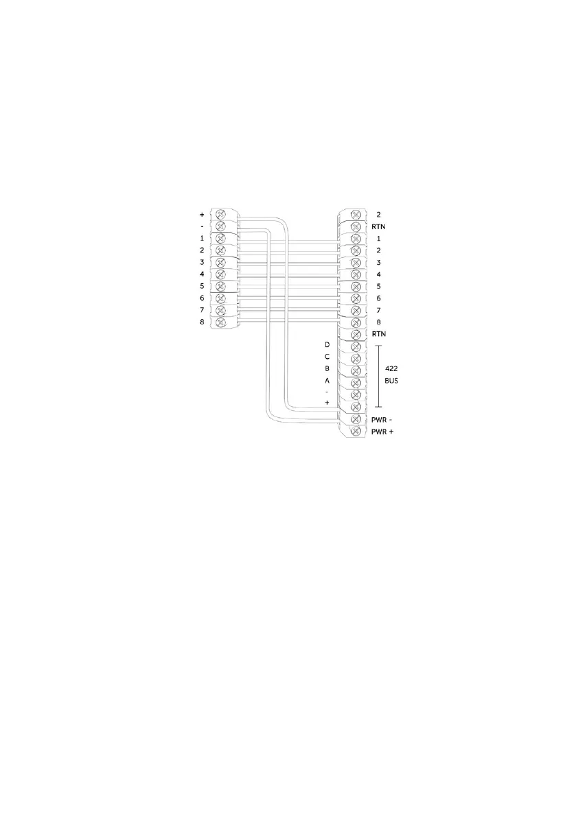
Figure 4 - Example of pin triggering wiring
Control Panel
DualCom Pro
PIN TRIGGERING
For this operation the device is triggered by removing or applying zero volts to input terminals 1-8. No external
pull-up resistors will be required. This is generally achieved via the digital communicator outputs of a control
panel. The unit will signal alarm conditions and will generate the relevant messages and forward them via the
Gemini Global Platform to the ARC. Installers are advised that the intended use should avoid situations where
the rate of trigger exceeds the rate at which messages are received at the ARC receiver.
PIN INPUT CONFIGURATION
If you need to change the input from negative removed to negative applied, this can be done on My Base. If you
need to use positive applied/removed you will need to change the pin profile on My Base and manually change
the bias on the device using the Self Learn feature:
• Ensure all required pins are in a restore/quiescent state and you are out of the device menu
• Press and hold the C button until L appears on the display
• Release the C button
• The display will confirm successful operation by displaying ‘LEARN OK’
7