GENERAL DESCRIPTION
Page 2-1
SYSTEM DESCRIPTION
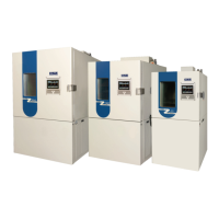
The ZP-Series Temperature chambers are pre-engineered chambers designed to provide
an environment with specifi c temperature (humidity) conditions. The standard ZP model is
composed of the following: 1. Controller, 2. Chamber, 3. Refrigeration/ Heating components.
Optional equipment includes, but is not limited to: 4. Humidity, 5. Pen Recorders, 6. High/
Low Limit, 7. IEEE-488 Serial Interface, 8. Boost Cooling System, 9. GN2 Purge, 10. Dry
Air Purge, 11. Limited Temperature Sheath Heaters.
The chambers have a standard range of -94ºF to +375ºF (-70ºC to +190ºC) cascade,
-50°F to +375°F(-45°C to +190°C) Tundra, and -30ºF to +375ºF (-34ºC to +190ºC) single
stage which provide both heating and cooling as required. Chambers with optional humidity
are designed to provide a minimum of 10% and a maximum of 98% relative humidity, as
limited by a 45ºF (7ºC) dewpoint and a 185ºF (85ºC) maximum dry bulb temperature. Refer
to Figure 2 for Achievable Humidity Points. The chambers are designed to operate in a
commercial environment, i.e. temperature of +75°F +/- 10°F (+23°C +/- 6°C), maximum dew
point of 55°F (12.8°C), and an altitude of 7,000 ft. (2133.6M). Refer to the specifi cations at
the end of this section for additional information.
CONTROLLER
The standard controller is composed of a CSZ EZT-570S Controller, a High/Low limit, and
communications electronics. Detailed operating instructions for the controller are found in
the controller user’s manuals on the digital media that accompanied the chamber. Other
optional controllers available include the Watlow F4. See Operating Instructions in Chapter
4 for more information regarding chamber controllers.
CHAMBER
A. Chamber Interior
The chamber interior consists of the front workspace and the rear component
area, separated by a stainless steel plenum cover. A probe bracket is behind the
grille in the upper left corner of the plenum. The bracket contains the probes for
the controller, recorder (if required), and RH sensor (if humidity option is installed).
The area behind the plenum cover contains the refrigeration evaporator coil,
heater limit thermocouple, evaporator fan(s), humidifi cation inlet (if humidity option
is installed), auxiliary cooling nozzle (if auxiliary cooling option is installed), and
the dehumidifi cation coil (if humidity option is installed). These items may only be
accessed by removal of the plenum cover by properly trained service personnel.
B. Chamber Exterior
Fiberglass insulation is used with a high temperature binder for temperatures up to
500ºF (260ºC). The cabinet is constructed with a minimum of mechanical contact
between the liner and the exterior to reduce conductive heat losses and minimize
condensation on the exterior cabinet.
A multiple-pane window assembly in the door of the chamber allows viewing of the
chamber interior during operation. The window is constructed of tempered glass
panes with a heater harness to assure frost-free viewing during low temperature
chamber operation. Under certain ambient conditions, it may be normal to see
some condensation around the outer window frame are a during low temperature
operation.
Condensation on
exterior surfaces is
normal when operating
at cold temperatures
for an extended period
of time.
NOTE
!