GENERAL DESCRIPTION
Page 2-13
CHAMBER PERFORMANCE
The performance of your chamber is signifi cantly affected by the characteristics
of your test sample. Factors including size, material, shape, weight and power
dissipation if energized. The test sample should be placed in the chamber in a
manner that allows proper ventilation. Air fl ow is taken in from the bottom of the
plenum and exits
from the top. Test samples should be placed on the shelves, not placed directly
on the chamber fl oor. Multiple test samples should be distributed throughout the
chamber to ensure proper airfl ow and minimize temperature gradients.
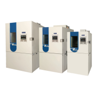
Shelves with product can be slid out of the chamber (approximately half way).
The "C" channel shelf rails will prevent the shelf from tipping. There is NOT a
mechanical stop to prevent the shelf from being pulled all of the way out. Shelves
pulled out more than half way can become unstable.
To relocate "C" channel rail remove shelf, lift front of rail up and pull forward. To
replace rail, place pin on rear of rail into the hole in the plenum and line up with slot
on shelf rail. Push rail back and then down locking rail into place.
Figure 9. Shelf in Pulled Out Position
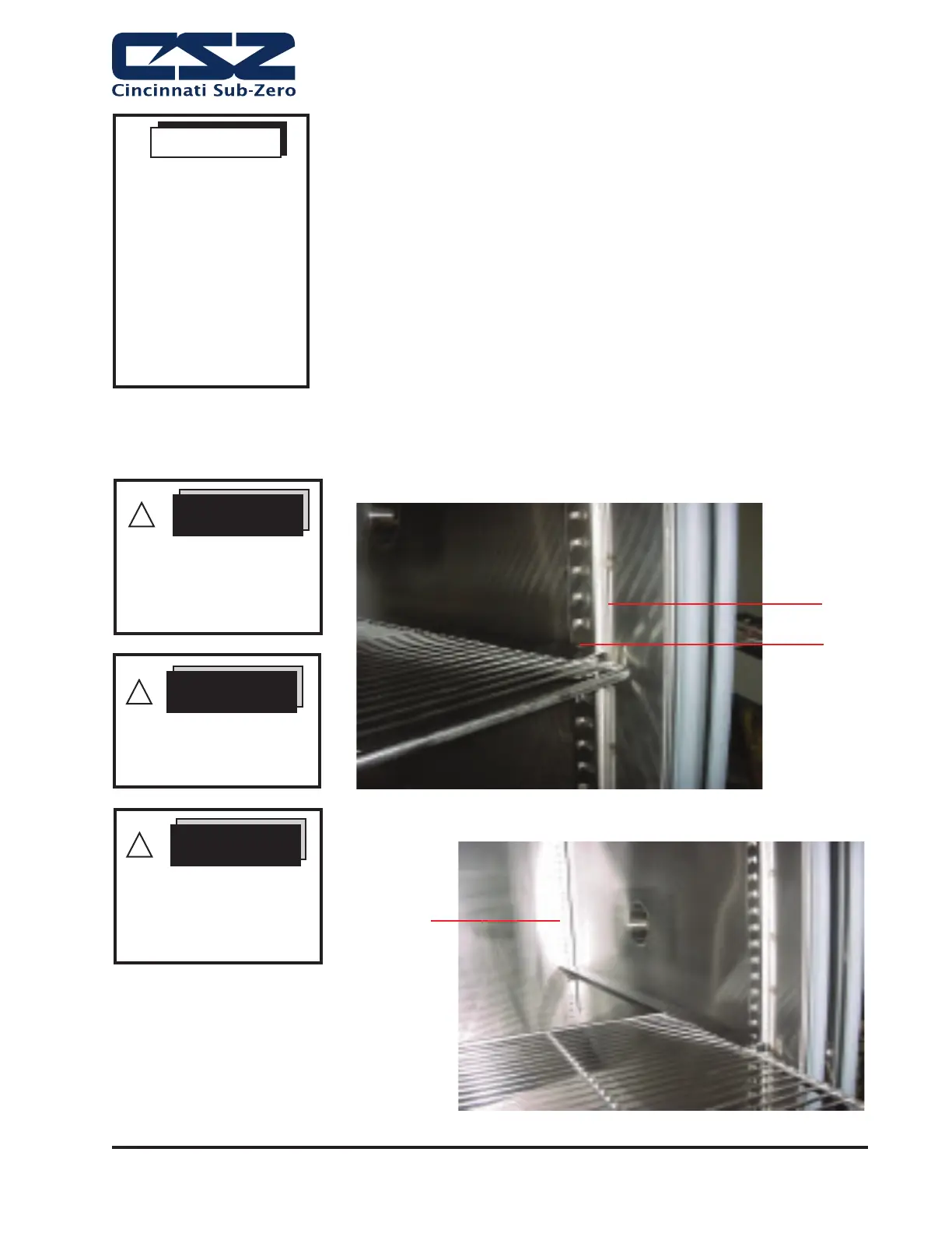
Figure 8. Shelf and Bracket
Shelf Rail
“C” Channel
Shelf Rail
SHELF DESCRIPTION
Test samples should be
placed in the chamber in a
manner that allows proper
ventilation.
WARNING
Shelves pulled more than
halfway out can become
unstable.
WARNING
“C” channel shelf rail is not a
mechanical stop to prevent
the shelf from being pulled
all the way out.
WARNING
!
!
!
Plenum Wall
with Holes for
Shelf Rail
If other devices are used
to take measurements
within the chamber, the
readings between the
chamber controller and
the other instruments
will vary slightly due to
the tolerances between
the two devices and
their individual sensing
elements.
NOTE
Note: CSZ is continuously upgrading the components used
in its equipment. Consequently, the physical appearance of
certain components may vary from that shown.