INSTALLATION
Page 3-8
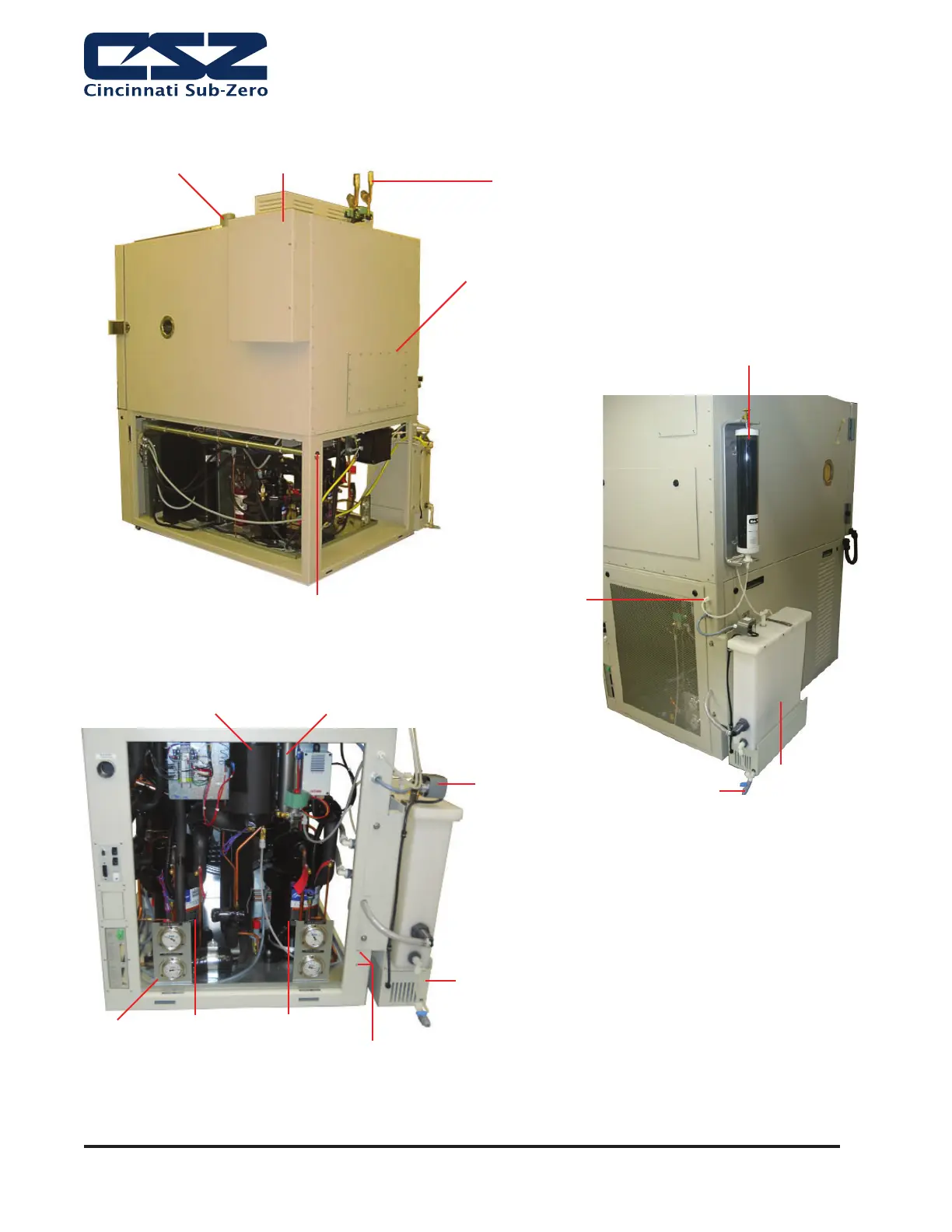
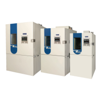
Figure 2. Installation Locations
R-508B
Compressor
System #2
R-404A
Compressor
System #1
Pressure
Gauges
Upper Refrigeration
Components located
behind access panel
Water Inlet
Location
Electrical Connection
LN2 Boost Valves
(Optional)
LN2 Vent
(Must be vented outdoors)
Dry Air Purge
(Optional)
Steam Generator
Assembly
Float Switch
Enclosure
Float Switch
Drain Valve
Pump
Recirculating Water
(Optional with Humidity)
Demineralizer Filter
(Optional with Humidity)
Water Cooled Condenser
Connections (If Applicable)
Note: CSZ is continuously upgrading the components used
in its equipment. Consequently, the physical appearance of
certain components may vary from that shown.