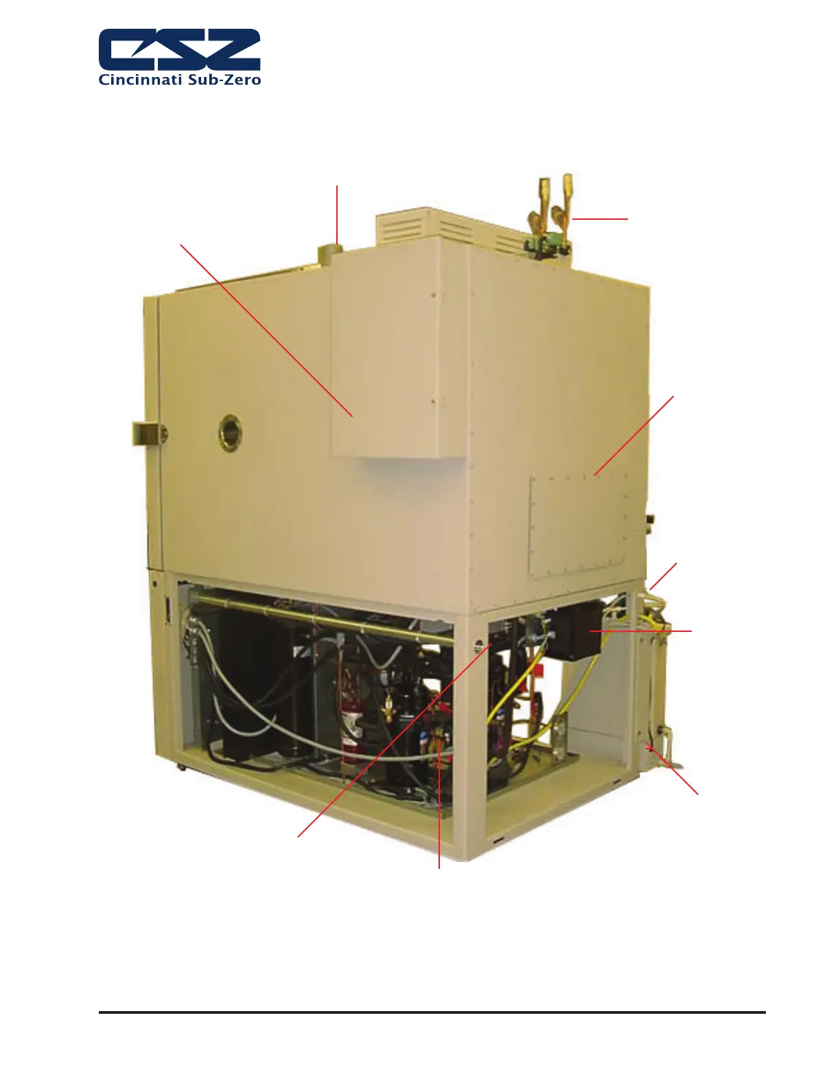
GENERAL DESCRIPTION
Page 2-3
Upper
Refrigeration
Components
(Located behind
access panel)
Water Cooled
Condenser Connections
(If Applicable)
Water Inlet
Location
Electrical Connection
(1 1/4” EMT Conduit - 35mm
Metric Conduit Trade Size)
LN2 Boost Valves
(Optional)
LN2 Vent
(Must be vented to outdoors)
Dry Air Purge
(Optional)
Steam
Generator
System
Lower Refrigeration Components
Figure 1. Chamber Components Location
Note: CSZ is continuously upgrading the components used
in its equipment. Consequently, the physical appearance of
certain components may vary from that shown.